Tools For Titanium
With all of the titanium that will be required for a new aircraft, any of 1,000 spindles might benefit from the tools and techniques described here.
Share


Watch the chips pile up in this video to get a sense of the metal removal rate this 10-flute end mill achieves in titanium.
The design of the new Boeing 787 Dreamliner relies extensively on composite materials. That aspect of the plane has received attention—rightly so. However, composites aren’t the only reason why this plane is materially different. Compared to other commercial aircraft, the 787 also uses significantly more parts made from titanium. To machine just the titanium necessary to fill the orders for this one aircraft, Boeing will need to employ 1,000 spindles within the next 3 to 5 years.
That estimate comes from Keith Young, an engineer/scientist with Boeing’s Advanced Manufacturing R&D group in Saint Louis, Missouri. Part of Dr. Young’s job is to help those spindles work more effectively for Boeing. The challenge of titanium aircraft parts is to make them lighter by making walls and floors thin, and by reducing the parasitic weight of stock remaining in corners. Through experiments, Dr. Young and others in this group develop machining techniques for achieving these goals. They tell Boeing’s designers what machined features are possible in titanium parts, and they educate machining suppliers about how to produce those features.
Some of this knowledge has already been developed for titanium parts in military aircraft. However, commercial aircraft differ in scale. Part dimensions, most significantly pocket depths, are bigger. A deep pocket in a military aircraft part is 3 inches. On 787 components, pockets in titanium can be 6 inches deep. Whereas tool length-to-diameter ratios of 3:1 or 4:1 have been traditional for machining aircraft titanium, the newer parts call for ratios of 6:1 or 8:1, and the difference fundamentally affects the choice of tooling. For example, where an inserted milling tool might typically feature a steel shank, the deeper pocket could call for a stiffer carbide shank to minimize deflection and help prevent chatter.
Tom Talley is another Boeing engineer/scientist in Saint Louis. Together, he and Dr. Young shared some of what they’ve learned about the tooling choices suited to the newest generation of titanium parts. Their recommendations provide the basis for this article, but it’s worth qualifying just how far those recommendations go. Boeing may endorse machining techniques, the two men say, but it doesn’t endorse cutting tool suppliers. Some tool suppliers are mentioned below because they offer what Mr. Talley and Dr. Young consider to be clear examples of useful tooling styles. However, in most of these cases, other tool companies do offer comparable designs. A competing tool might be the more effective choice in a particular shop’s process. The tools cited here are simply illustrations, showing some tool features suited to the part features that are increasingly important to Boeing.
Tools For Roughing
The Weldon Crest-Kut tool shown in Figure 1 features irregular geometry along the flutes. The importance of this irregularity has to do with eliminating chatter.
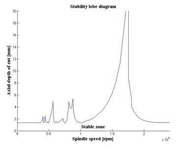
Chatter is the limiting factor in many milling processes. Its severity at a certain depth of cut often prevents the tool from achieving the much heavier depth of cut that the tool and the spindle would otherwise allow. Chatter is partially caused by the regular waviness that a tool’s consistent geometry imprints upon the machined surface. With the inconsistent form of these flutes, the tool fails to impart these regular waves. Thus, the “signal” that might feed the potential for chatter is much weaker. As a result, this tool can cut efficiently and quietly at a depth of cut that may represent a significantly higher rate of metal removal.
An entirely different option for achieving a high metal removal rate in titanium is plunge roughing. For aircraft parts made of aluminum, plunge roughing rarely makes sense; milling in the conventional way is fast enough. In titanium, however, plunge roughing may offer a way to bypass an otherwise slow cut to hog a lot of material quickly.
Plunge roughing feeds the milling cutter into the stock like a drill. Material is machined away through overlapping plunges, with each plunge taking advantage of the machine’s inherent stiffness along the Z direction. The center-cutting tool from Iscar shown in Figure 2 is an example of the kind of tool that can do this work.
Dr. Young says there are two cases in titanium where plunging in Z is likely to make sense. Those cases are 1) pockets that are shallow and wide, and 2) pockets that are narrow and deep.
In a pocket that is shallow, a deep-cutting end mill such as the Weldon tool may not be able to achieve enough axial depth to realize its full effectiveness. If that same pocket is wide enough to accommodate a series of plunges with a fairly large-diameter tool, then plunge roughing may be more efficient.
In a pocket that is narrow and deep, on the other hand, an end mill may spend too much time ramping instead of milling productively. The plunge roughing tool can machine such a pocket simply by plunging deep with each pass.
Whatever the choice of tool and technique for removing a lot of stock quickly, it’s important to note that not all titanium parts present this challenge. That is, not all of them require roughing. Newer titanium parts may begin as laser depositions—near-net shape parts for which only finishing is required. Finishing is also where the machining process realizes the part’s value by producing the challenging features. For these reasons, says Dr. Young, the choice of finishing tools is even more significant than the choices related to roughing.
Finishing Floors And Corners
Figure 3 shows an end mill from Data Flute that also uses irregular geometry to discourage chatter. The four flutes are spaced at increments slightly off from 90 degrees. Placing the irregularity at the tip in this way is appropriate, because when this tool finishes the floor of a pocket, the tip is where it does its work.
Chatter is an even more significant danger in finishing operations. In roughing, chatter inhibits productivity. In finishing, however, the part itself may be at stake, because chatter may compromise accuracy and finish, or it may even destroy delicate features such as the thinnest ribs and walls. Whether or not there is an irregular geometry, therefore, tools for finishing titanium generally should be rigid in order to minimize chatter’s potential. The same rigidity can reduce the danger of deflection deep in the pocket.
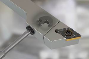
Figure 4 shows an example. This plunge finishing tool from Ingersoll Cutting Tools can machine a small corner radius into a deep pocket by feeding in Z. Dr. Young points to this type of tool as a case where a carbide shank may be needed in place of a steel shank to maximize rigidity.
Finishing Walls And Ribs
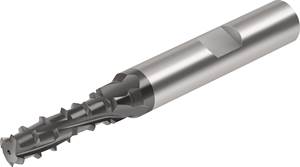
Figure 5 shows a 10-flute tool design, also from Data Flute, that can be effective at machining thin walls and ribs for titanium parts. Because feed rate is a function of both the flute number and the chip load, this tool can traverse the part quickly, even when the chip load is light.
The tool’s shallow flute depth enhances rigidity. Because the tool is intended for light depths of cut, this shallow depth is all that is needed. The result is a large core diameter that keeps the tool stiff. The short flute length helps with rigidity as well.
Yet another potentially important feature of the tool is not visible here. Tools that finish walls and ribs in titanium should feature eccentric relief along the flutes, Mr. Talley says. By interacting with the machined surface, this relief can damp the process to inhibit chatter. (See the box on the facing page to find video of how productively these features can enable the tool to cut. Dr. Young says the tool shown in the video is a 10-flute tool from RobbJack.)
Shops accustomed to machining thin walls in aluminum aircraft parts may already know how to use an end mill to machine those features in titanium. Through “waterline machining,” the tool should cut from both sides of the feature in alternating passes, so that the wall or rib remains supported from both sides as the feature is revealed.
As for how much stock the finishing tool should remove in this way, Dr. Young says the tool itself provides a clue. As a rule of thumb, the height-to-thickness ratio of the stock that is left behind after roughing should match the length-to-diameter ratio of the tool that will do the finish machining.
In other words, if a tool with an L:D of 6:1 will finish the rib, then the stock after rough machining should only be about 1/6 as thick as the height of the unfinished rib.
Again, this is just a rule of thumb, one that certainly does not account for the different elastic moduli of the tooling and the workpiece. However, the underlying point is this: The wall or rib still supported by remaining stock should be about as stiff as the finishing tool, and no stiffer.
Making the supported feature stiffer wastes time and tool life by leaving excess stock for the finishing tool to remove. The extra stiffness provides no benefit, because deflection is deflection, whether it is the tool or the part that deflects. If a particular stiffness has already been determined to be appropriate for the tool, then that same stiffness is also appropriate for the material the tool will be cutting.
Related Content
Selecting a Thread Mill That Matches Your Needs
Threading tools with the flexibility to thread a broad variety of holes provide the agility many shops need to stay competitive. They may be the only solution for many difficult materials.
Read MoreHow to Troubleshoot Issues With Tool Life
Diagnosing when a tool is failing is important because it sets an expectation and a benchmark for improvements. Finding out why gives us a clue for how to fix it.
Read MoreQuick-Change Tool Heads Reduce Setup on Swiss-Type Turning Centers
This new quick-change tooling system enables shops to get more production from their Swiss turning centers through reduced tool setup time and matches the performance of a solid tool.
Read MoreHigh-Feed Machining Dominates Cutting Tool Event
At its New Product Rollout, Ingersoll showcased a number of options for high-feed machining, demonstrating the strategy’s growing footprint in the industry.
Read MoreRead Next
Ten Questions About Chatter
If you want to use a high speed milling spindle to machine aggressively, then information about chatter should be more than just background noise. Here are some basics.
Read MoreBuilding Out a Foundation for Student Machinists
Autodesk and Haas have teamed up to produce an introductory course for students that covers the basics of CAD, CAM and CNC while providing them with a portfolio part.
Read MoreSetting Up the Building Blocks for a Digital Factory
Woodward Inc. spent over a year developing an API to connect machines to its digital factory. Caron Engineering’s MiConnect has cut most of this process while also granting the shop greater access to machine information.
Read More


