Toolholder System Gives Stable Cutting
There is no doubt that machine tool spindle speeds are climbing. Just look at the standard speeds offered on machining centers five years ago compared to those speeds offered as standard today.
Share


ECi Software Solutions, Inc.
Featured Content
View More


There is no doubt that machine tool spindle speeds are climbing. Just look at the standard speeds offered on machining centers five years ago compared to those speeds offered as standard today. With higher rates of rotation comes increasing sensitivity to dynamic changes in the cutting toolholder and spindle interface.
At high rotational speeds, the taper bore of a typical machine tool spindle tends to open up slightly due to the influence of centrifugal force. Because a typical V-flange toolholder is only in contact with the taper bore, it can be pulled up into the spindle under dynamic conditions. This can change the gage line measurement of the tool, which is generally set statically. Accuracy of the cut can be affected.
Nikken Kosakusho Works, Ltd. of Osaka, Japan (represented in the United States by Heartech Precision Inc., Elk Grove, Illinois) has developed the 3lock toolholder that overcomes high speed disadvantages of conventional V-flange taper toolholders.
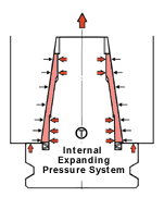
Nikken's toolholding system uses a spring-loaded shell around a solid V-flange to pre-load the toolholder in the spindle bore. A slit in the shell that allows movement is visible. At high speed, centrifugal force causes the spindle bore to grow. The preloaded shell rises under spring pressure to expand with the spindle and maintain solid contact between the holder and the spindle bore.
One of the more popular solutions to the problem of spindle "bell-mouthing," as expanding spindle taper is sometimes referred to, is to create a toolholder design that contacts both the spindle taper and the spindle nose. This simultaneous contact locks the toolholder radially and axially, creating a more rigid connection. Contact of the toolholder with the spindle nose flange keeps the toolholder from moving up the spindle bore at high speeds. Additionally, the taper and face contact helps keep the toolholder from deflecting under cutting forces generated in the feed direction.
Probably the best known example of the concept of simultaneous face and taper contact is the HSK toolholder. What Nikken's toolholder does for the shop is it allows a choice of using existing V-flange tooling or the 3lock system as applications dictate. HSK, on the other hand, excludes the use of any toolholder design that is not HSK.
Moreover, the 3lock toolholder approaches taper and face contact with an active system that effectively pre-loads the toolholder's taper against the spindle bore, allowing it to compensate for any dynamic changes in the spindle bore due to centrifugal force. This active system consists of a solid conical core, like a traditional V-taper toolholder, inside a cone shaped shell. The shell has a slit that runs axially, allowing it to move independently of the solid core. Between the slit shell and the taper flange is a Bellville disc spring. When the holder is pulled into the spindle bore by the drawbar, the spring compresses. The spring loading beneath the taper flange of the toolholder creates a preload on the shell, resulting in the full taper contact along the spindle bore.
Normally when a toolholder is inserted into a machine spindle there is a 4 mm gap between the spindle face and the top of the toolholder flange. Nikken's toolholders have an extra 2 mm of stock on the flange. The remaining gap between the toolholder flange and the spindle nose is closed by using precision-machined shims. Once the gap is accurately measured using a plug gage supplied by Nikken, these shims are put in place to close the gap and provide the spindle face contact for the toolholder. Gap variances between different spindles are accommodated using this system.
When the toolholder is drawn into the spindle bore by the drawbar, the spring-loaded shell compresses against the tapered bore. The drawbar action stops when the toolholder flange makes contact with the spindle nose. Full force of the drawbar is maintained regardless of the spindle speed.
Statically, the toolholder shell is now in compression. As the spindle rotates to speed and the spindle bore begins to bell-mouth, the shell rises to compensate for the spindle's expansion and maintain taper contact. The result is a more stable connection under dynamic cutting conditions. Because of the nose contact, the toolholder body cannot be pulled deeper into the spindle bore as it expands. This keeps the gage line measurement constant for better accuracy.
According to the company, a damping zone is created by the disc spring at the bottom of the taper shell. It acts like a shock absorber. This damping effect allows the toolholder to absorb cutting generated vibrations and slight out-of-balance conditions so the cutter can run faster and the tool itself last longer.
Read Next
5 Rules of Thumb for Buying CNC Machine Tools
Use these tips to carefully plan your machine tool purchases and to avoid regretting your decision later.
Read MoreRegistration Now Open for the Precision Machining Technology Show (PMTS) 2025
The precision machining industry’s premier event returns to Cleveland, OH, April 1-3.
Read MoreBuilding Out a Foundation for Student Machinists
Autodesk and Haas have teamed up to produce an introductory course for students that covers the basics of CAD, CAM and CNC while providing them with a portfolio part.
Read More


.jpg;maxWidth=300;quality=90)


