The Case For Copy Milling Cutters
The round-insert 'button cutter' can bring a high metal removal rate to a low horsepower machining center.
Share


Hwacheon Machinery America, Inc.
Featured Content
View More

The work of indexable milling tools is often accompanied by vibration that is a familiar sound—and a familiar feel—in many shops. When these tools are run at heavy depths of cut to achieve high metal removal rates, the productivity may come at the expense of the corner of the cutting tool and the life span of the machine.
One alternative that can provide a smoother cut, in addition to many expanded capabilities, is the copy mill. "Button cutter" is another name for this type of tool.
The copy mill is a simple variation on the traditional end mill, in that the copy mill uses circular insert geometry as opposed to traditional parallelogram or square inserts. This difference delivers a variety of benefits, most of which complement today's trend toward lighter depths of cut and faster feed rates, or high speed machining. This article discusses each of these benefits individually:
- Plunging capability
- Enhanced helical milling and ramping
- Stronger cutting edge
- Larger number of usable edges
- High metal removal rate with low power
- Roughing closer to finish form
Plunging
Some copy mills possess the ability to plunge directly into the material, similar to a drill. This is particularly true of the end mill version of the copy mill, but only where the manufacturer has built in sufficient clearance on the bottom of the tool to permit cutting in this direction. Direct plunging is also possible with a shell mill version of the tool, but most shops would find this to be such a large horsepower drain that they would be better off ramping.
A copy mill can't take the place of a drill; the surface area engaged is too large to continue this way much beyond the desired depth of cut for milling. However, the ability to plunge during milling removes a common machining headache: the need to drill a start hole prior to roughing.
A conventional indexable end mill requires this drilled start hole because the tool is not able to execute a straight Z-axis move into the material. The only other way to enter the material with this type of cutter is a ramp-in entry, which typically calls for CAM software. However, with a copy mill, this step can be avoided. Plunging can be programmed into the control's canned pocketing cycle without concern for the tool's entry. This freedom to plunge is particularly helpful in more complex cavity roughing or surface roughing routines, where a CAM package may interject numerous plunge points in order to complete the roughing tool path. With copy mill cutting tools, these plunge points are no longer a concern.
Helical Interpolation
Larger diameter hole making can be quick and easy when a copy mill is used in combination with helical interpolation. This technique resembles thread milling in that all three axes (X, Y and Z) are in motion simultaneously. It differs from thread milling in that the tool is introduced into the material without a start hole of any kind. The tool simply is positioned at the inside diameter of the hole to begin its helix from there, achieving complete material removal from the hole by ramping down to the final depth. This smooth operation tends to avoid the high horsepower consumption characteristic of large diameter hole making. And with the high clearance angles of copy mill cutting tools, ramp angles during helical interpolation can be aggressive, without concern for rubbing the bottom of the cutting edge. The quick and easy process offers the added advantage of allowing many different hole sizes to be generated with the same diameter tool. Hole size variation is all in the programming.
A representative comparison illustrates the potential efficiency improvement from this technique. (See shaded box on the next page.)
Edge Strength
With no corners to break, a round insert provides the strongest cutting edge available in an indexable carbide insert. The strength comes in handy when operating in a heavy cut, or when attempting roughing cuts under unstable conditions. When cutting with a long-reach tool, the round inserts are more forgiving of tool deflection and chatter, allowing speed and feed rate to be increased with less danger of insert chipping.
Cutting forces are also distributed more effectively. With a typical 90-degree cutting tool, the majority of the tool pressure is radial, resulting in high deflection and increased potential for chatter or breakage. The round cutting edge spreads the force more evenly, directing a larger percentage of the tool pressure into the axial direction. This too is desirable when cutting with longer-length tools, because the reduced radial pressure reduces deflection.
But beware of this condition when using a horizontal machining center. The increased axial pressure may cause flexing in the workholding, which typically is mounted on a tombstone or angle plate that isn't as well supported as the solid base of a vertical machining center. On an HMC, this flexing can result in micro chipping of the insert from the subtle vibrations that occur with the flex. Tool life will be shortened, and cutter breakage is more likely. To reduce or eliminate this problem, try positive axial rake cutters, which minimize the downward push into the workpiece.
Number Of Edges
Round inserts provide the additional benefit of offering a larger number of usable edges than typical carbide inserts. Depending on the size of the insert and the depth of cut, a round insert can provide from four to eight effective indexes, yielding at least twice the total material removal and minutes in the cut of a typical parallelogram or square. This advantage translates to fewer trips to the tool crib for new inserts (keeping the operator at the machine and the tool in the cut), fewer inserts to stock in inventory (lowering on-hand inventory costs) and a lower cost per cutting edge.
For example, the typical parallelogram insert costs about $8. With two usable edges, the cost per edge is $4. A square insert (which usually does not perform as well as a parallelogram because of the lack of a positive topography and axial relief) may cost $10. This comes to $2.50 per edge.
Compare these costs to that of a typical round insert. This insert may cost as much as $11 (many are less). At this cost, the worst-case scenario—heavy cutting permitting only 4 indexes—yields a cost per edge of $2.75. The more typical scenario, 8 indexes, yields a cost per edge of $1.38. These costs, particularly in applications where the round insert delivers more metal removal per minute than other inserts, make the economics of the tool attractive.
Metal Removal With Low Horsepower
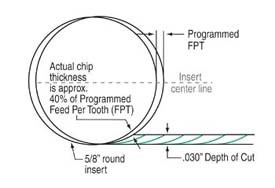
Applied correctly, round inserts can yield impressive material removal rates without a demand for impressive horsepower. The strength of a round insert permits feed rates that would not be possible with 90-degree cutting tools, allowing even lighter-duty machines to perform aggressive roughing. The key point to understand with a round insert used in this way is that heavier depths of cut lead to higher chip thickness, which increases horsepower consumption. (See Figure 1.) By taking light cuts—0.025 to 0.050 inch depth of cut—the typical round-insert cutting tool can feed at rates in steel around 0.040 inch per tooth, and in certain cases as high as 0.060 inch per tooth. By comparison, most parallelogram or square inserts reach their limit at 0.010 to 0.012 ipt.
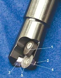
It is important to note that some users of button cutters have experienced problems with insert movement in the pocket of the cutting tool during cutting, or when the insert is worn. In either of these cases, tool pressure increases and the effectiveness of the insert clamping can be compromised. The cutter should include design characteristics that strengthen tool integrity for these applications. Some cutters, for example, use screw-through inserts accompanied by extra top clamps. These cutters provide the security of double clamping for each insert.
Another important feature is positive locking in the insert seat. Many button cutters use inexpensive molded inserts that have round sides, providing no radial locking for the insert. Tangential cutting forces on an insert such as this may cause the insert screw to lose torque. More rigid copy mills address this problem with locking surfaces on the sides of the inserts—locating flats that mate with matching flats on the cutter body, leaving little chance for movement.
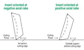
Finally, look for tools providing maximum support for the cutting edge, particularly if high feed rate is the goal. Copy mill cutters using negative axial rake (tipping the insert down toward the workpiece) can cut well using conservative parameters but fall short during more aggressive metal removal. Inherent in the design is a lack of support for the primary area of force, which is right at the cutting edge. (See Figure 2.) Copy mill cutters using positive axial rake provide much better cutting edge support because the carbide behind the cutting edge is closer to being parallel with the cut. Positioning the carbide in this way lets the end user take advantage of the carbide's ability to absorb high compressive forces.
But in this scenario, toolholding rigidity is important. Stub-length end mill holders or shell mill holders are highly recommended.
With the right tooling, even machine tools with only 10 or 15 hp are capable of competitive metal removal, resulting in fewer setups and greater flexibility in shopfloor scheduling.
Roughing Closer To Finish Form
The use of a round insert for roughing applications opens up new possibilities in the preparation for semifinish or finish cuts. When roughing with 90-degree cutters, each step down (or each pass during Z-level roughing) leaves a "stair step" behind. The heavier the depth of cut with each pass, the more dramatic this stair-step effect. The resulting uneven surface leads to uneven pressure on the semifinish tool. This shocks the tool and also causes varying deflection, making direct progression from roughing to finishing out of the question. Not only is a semifinish pass required, but multiple finish passes may be needed as well.
Using round inserts dramatically reduces this effect. In place of the steps left by the 90-degree tool, the surface has much smaller "scallops" that are low in height and easier to machine through. This effect is complemented by the fact that round inserts are optimally applied at lighter depths of cut, because the lighter depth makes the scalloping even less dramatic. The stock remaining after roughing is more even, yielding a surface that can be semifinished aggressively, or in some cases can be finished without the semifinish step.
About the author: Michael Bitner is a product manager for cutting tool supplier Dapra Corporation (Bloomfield, Connecticut).
Related Content
How to Mitigate Chatter to Boost Machining Rates
There are usually better solutions to chatter than just reducing the feed rate. Through vibration analysis, the chatter problem can be solved, enabling much higher metal removal rates, better quality and longer tool life.
Read MoreFinding the Right Tools for a Turning Shop
Xcelicut is a startup shop that has grown thanks to the right machines, cutting tools, grants and other resources.
Read MoreToolpath Improves Chip Management for Swiss-Type Lathes
This simple change to a Swiss-type turning machine’s toolpath can dramatically improve its ability to manage chips.
Read MoreForm Tapping Improves Tool Life, Costs
Moving from cut tapping to form tapping for a notable application cut tooling costs at Siemens Energy and increased tool life a hundredfold.
Read MoreRead Next
5 Rules of Thumb for Buying CNC Machine Tools
Use these tips to carefully plan your machine tool purchases and to avoid regretting your decision later.
Read MoreRegistration Now Open for the Precision Machining Technology Show (PMTS) 2025
The precision machining industry’s premier event returns to Cleveland, OH, April 1-3.
Read MoreBuilding Out a Foundation for Student Machinists
Autodesk and Haas have teamed up to produce an introductory course for students that covers the basics of CAD, CAM and CNC while providing them with a portfolio part.
Read More




.jpg;maxWidth=300;quality=90)


.jpg;maxWidth=300;quality=90)


