Successful Application Of Ceramic Inserts
Applying ceramic inserts is not a simple substitution of one cutting tool material for another. There are significant process considerations that shops should examine carefully in order to realize performance and tool life expectations from ceramic inserts. Here's a look at some of the ways they are used.
Share


There's an axiom in metalworking that urges the use of the right tool for the job. In an increasing number of applications, the right tools for the jobs are ceramic cutters. While available as solid body tools, the most popular form of ceramic cutters is the indexable ceramic insert. It is a highly productive tool for milling and turning applications.
Almost every shop uses indexable inserts. Their application in metalworking has produced benefits for shops of all kinds through improved cutting performance and tool life, reductions in tooling costs and simplified changeover.
Among carbide indexable inserts there is a huge selection of shapes, substrates, coatings and geometries from which to choose. Likewise there are different kinds of ceramics. In this article we will concentrate on ceramic inserts that use silicon carbide crystals to reinforce the base ceramic compound. The silicon carbide reinforcements of these ceramic inserts are often referred to as whiskers because they resemble small hairs when examined under a microscope.
To find out more about ceramic inserts and especially how their application in metalworking differs from carbide inserts, we talked to Keith Smith, manager marketing and international sales for Greenleaf Corporation (Saegertown, Pennsylvania). Greenleaf introduced whisker reinforced ceramic inserts to the United States and has extensive experience in their successful application in metalworking shops.
What Are Reinforced Ceramics?
Chemically, the main ingredient in Greenleaf's ceramic insert cutters is alumina (Aluminum Oxide). It's a very hard substance that has for many years been used in grinding wheels. Basically, a ceramic insert is a very fine-grained aluminum oxide grinding wheel. The biggest difference between the two cutting tools is that the insert is manufactured without the porosity necessary for grinding.
During the manufacturing process, reinforced ceramic is pressed into insert blanks which are subsequently cut to the desired shape. They are subjected to a much more extreme bonding process than the sintering used for carbide. Usually whiskered ceramic undergoes a hot pressing process that uses external heat and high pressure, evenly distributed, to compress the insert blank and eliminate porosity.
Many of the inherent cutting advantages of the grinding process—high heat tolerance, excellent surface finish, long tool life—transfer to milling and turning operations with the application of ceramic inserts.
Probably the major down side of the ceramic insert is its brittleness. Generally ceramic cutters don't hold up well to interrupted cuts or thermal shock. To help alleviate this performance constraint, small crystals of silicon carbide are put into the aluminum oxide compound.
In Greenleaf's insert, the ratio is about 50/50 alumina to silicon carbide whiskers. These crystals are like fibers and act as reinforcement to the brittle ceramic. They act in much the same way as glass threads reinforce resin in fiberglass.
"Whiskered ceramic, like all cutting tool materials, has specific areas of application that are best suited to its capabilities," says Mr. Smith. "In general, it works best on hard ferrous materials and nickel base alloys. It does not work on ferrous materials below 42 Rc because some reaction problems occur. We find about 80 percent of reinforced ceramic usage is on nickel alloys and aerospace alloys such as Inconel, Waspoloy, Hastelloy and others."
In The Cut
It is within the metalcutting operation that ceramic cutters earn their stripes. While much research has been conducted to describe the dynamics of chip formation, one common factor found in all of the theories is that much heat and stress gets generated as a cutting tool displaces the metal.
The winners in this nasty environment must be very hard materials that are resistant to heat and that are geometrically as well as chemically stable. In general, the operational variable needed to be successful is speed—faster cutting generates more heat.
Every insert has a melting point, which reflects the temperature at which it is made. Ceramic's melting point (3,700° F) is higher than sintered carbide, which means it can be driven through the cut faster.
Hard Turning And Milling
Turning is an almost ideal operation for ceramics. In general, it is a continuous machining process that allows a single insert to be engaged in the cut for relatively long periods of time. This is an excellent vehicle to generate the high temperatures that make ceramic inserts perform optimally.
Milling, on the other hand can be compared to interrupted machining in turning. Each insert on the tool body is in and out of the cut during each revolution of the cutter. Compared to turning, hard milling demands much higher spindle speeds to achieve the same surface speed.
To match the surface speed of a turning operation on a three inch diameter workpiece, a three inch diameter milling cutter with four teeth must run four times the turning speed. With ceramics, the object is to generate a threshold of heat per insert. Therefore in milling operations, each insert must travel faster to generate the heat equivalent of a single point turning tool.
What's So Special?
Ceramic cutters in many cases demand a new set of application skills from the shop looking to implement them. Often the process knowledge acquired from sintered carbide insert use is 180 degrees opposite the experience needed to use ceramics.
"It's very important for shops to understand that the way whiskered ceramic inserts work is completely different from other cutting materials," says Mr. Smith. A major difference is the way ceramics use heat generated in the cut.
In most traditional metalcutting, heat is the enemy. It's bad for the tool and generally bad for the workpiece (work hardening). The heat dissipation objective for most carbide cutting inserts is to get heat into the chip and quickly out of the cut zone.
Not so for ceramics, says Mr. Smith. "We set out to generate high temperature ahead of the cutting tool in order to soften or plasticize the workpiece material to facilitate its removal. The ideal cutting temperature in nickel alloy, for example, is in the area of 2,200° F. This cutting temperature is beyond the tolerance range for sintered carbide because 2,200° F is close to the melting point of cobalt, which is what cements the carbide insert together. At these temperatures, carbide will soften, deform and fail."
To achieve the elevated operating temperatures for ceramic inserts to prove their mettle, much higher cutting speeds are suggested. "Beyond all question," emphasizes Mr. Smith, "successful cutting with ceramic inserts demands high surface speed coupled with balanced feed rates. High speed cutting is necessary to generate the high heat within the cutting zone and to assure that the heat propagates into the workpiece immediately ahead of the cutter."
In general, a conservative approach to cutting speeds and feeds is the single largest contributor to process failure when trying to implement ceramic cutters. When cutting speeds are too slow, insufficient heat is generated. Because heat cannot be transferred ahead of the cutter, in effect, to anneal the already hardened workpiece, cutting forces become too high and insert failure occurs.
In most cases, insert failure is a sign to the machinist to back off speeds and feeds even more. In the application of reinforced ceramic insert cutters, that is the wrong thing to do and only exacerbates the situation.
How Fast Is Fast?
Assigning numerical values to optimum high speeds and feeds for cutting with ceramics is difficult because of the many process variables that constitute each application. There is, however, an empirical method of analyzing how close a machining operation using ceramic inserts is to optimum.
"When the correct speed to heat generation ratios are in effect," says Mr. Smith, "the chip produced will be bright red or almost white hot. This is normal for ceramic cutting tools but perhaps is a bit unusual for the machinist or operator who is taught to perceive red or white hot chips as dangerous or undesirable."
Rethink Conventional Wisdom
For shops looking to use ceramic cutters, there are several key points that, if followed, will help make the implementation smooth and the machining successful. Some of these are intuitive, others are generally good shop practice and a few others are ceramic specific.
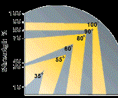
The relatively high cutting speeds necessary to generate optimum heat put a strain on the cutting insert. Whenever possible the strongest insert shape should be selected. According to Greenleaf these shapes are—in descending order from strongest to weakest—round, 100-degree diamond, square, 80-degree diamond, triangle, 55-degree diamond and 35-degree diamond.
In addition, the larger the corner radius, the stronger the corner. In roughing, for example, use a large radius to rough the workpiece and then finish with a smaller tool nose radius.
Tool holder stiffness is a critical consideration for ceramic machining operations. Deflections will create vibrations that are especially damaging to ceramic cutters, not to mention the surface finish of the workpiece. The shortest overhang possible is the best setup, and the thicker the tool shank or boring bar diameter, the better for cutting with ceramics.
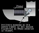
For roughing operations, the programmer should consider varying the depth of multiple roughing passes. Multiple passes at the same depth tend to wear an insert in the same area causing a notch to form. Varying the depth spreads the wear patterns over a larger section of the insert.
Another depth-of-cut strategy for flat-sided ceramic inserts is to program fewer passes but deeper ones in order to bury the insert deeper in the workpiece. This moves the notch formation farther up the face of the insert to an area that has a stronger cross section. "The best solution to is to program the cut using ramping techniques which avoid a fixed depth of cut altogether," says Mr. Smith.
It's A Cutting System
Applying ceramics is more than simply slapping on an insert and going at the work. The entire process, which is all factors needed to deliver the cutter to work, is involved to a high degree.
Cutting with ceramic tools puts a strain on the machine tool. High cutting forces, coupled with aggressive feeds and high spindle speed are like red-lining your car. Everything has to be in proper tune, or a failure will occur.
While machining with ceramics doesn't necessarily require special machine tools, the process does demand that the machine be in tip-top shape. "High surface speeds and aggressive cutting depths will push a machine to its design limits," says Mr. Smith. "Lubrication of the linear way systems, spindle bearings and ballscrews should be confirmed as up to spec. Gibs and backlash adjustments too should be tweaked to eliminate any looseness in the machine tool motion."
If the operation is run wet, coolant delivery and capacity should be sufficient to flood the cutting zone to consistently maintain the average temperature of the insert and to reduce any possible thermal shock, thereby increasing tool life. "Coolant volume is more important than pressure in ceramic cutting applications," says Mr. Smith. "While reinforced whisker inserts are much less susceptible to thermal shock from inconsistent coolant application and mechanical shock from interrupted cuts, it's better to be safe than sorry."
When machining interrupted cuts with reinforced ceramics, velocity of the cutter is a critical parameter. "Whiskered ceramic inserts are very strong," says Mr. Smith. "They can take interruptions in the workpiece surface. However, it's very important to keep the speed up in these applications."
A rule of thumb for interrupted cuts is to estimate the percentage of voids in the surface and then increase cutting speeds by that percentage. Calculate the circumference of the workpiece then subtract the sum total of interruptions.
In effect this calculation gives a smaller diameter. The rotational speed for the calculated smaller diameter should then be increased to the value of the original surface speed in order to offset the loss in heat generation created by the voids.
Different Wear Patterns
Normal wear patterns for reinforced ceramic inserts are unlike wear patterns seen on carbide inserts. Many shops waste money by tossing ceramic inserts prematurely.
According to Mr. Smith, ceramic inserts show flaking along the cutting edge. "Flaking off of small pieces around the top periphery of the insert is a result of pressures caused by flank wear. In roughing operations, where surface finish is not a critical concern, this type of tool wear is generally not a concern. In many cases, it's a benefit because the flaking, almost like chipping flint, exposes a new sharper edge."
A tell-tale sign of flaking in ceramic inserts is sparking that can be seen moving up the face of the insert. This is caused by friction from the chip as it passes over the roughened surface of the insert.
Is It For You?
Applying ceramic cutters is different but it's not alien. For many jobs in the 45 to 65 Rc hardness range, in which grinding was historically the process of choice, hard turning and hard milling with ceramic insert cutters are finding increasing acceptance in shops. Impressive cycle time reductions, of several orders of magnitude, can be achieved with ceramics versus carbide.
Related Content
The Future of High Feed Milling in Modern Manufacturing
Achieve higher metal removal rates and enhanced predictability with ISCAR’s advanced high-feed milling tools — optimized for today’s competitive global market.
Read MoreForm Tapping Improves Tool Life, Costs
Moving from cut tapping to form tapping for a notable application cut tooling costs at Siemens Energy and increased tool life a hundredfold.
Read MoreHigh-Feed Machining Dominates Cutting Tool Event
At its New Product Rollout, Ingersoll showcased a number of options for high-feed machining, demonstrating the strategy’s growing footprint in the industry.
Read MoreCustom PCD Tools Extend Shop’s Tool Life Upward of Ten Times
Adopting PCD tooling has extended FT Precision’s tool life from days to months — and the test drill is still going strong.
Read MoreRead Next
Are You Turning Fast Enough?
Let's face it. When most shops go looking for process improvements, turning is seldom at the top of the list. Sure, many shops these days are doing fine work in such areas as reducing lathe setup, combining milling and turning operations on a single machine, and automating workpiece handling functions. But for all the talk of high speed machining and other milling and drilling process improvements, precious little of that kind of thinking is being applied to the turning process itself.
Read MoreExtending The Range Of PCBN
Thicker inserts and a wider variety of styles are allowing PCBN to be applied to a growing range of hard, ferrous applications.
Read More5 Rules of Thumb for Buying CNC Machine Tools
Use these tips to carefully plan your machine tool purchases and to avoid regretting your decision later.
Read More




.jpg;width=860)


.jpg;maxWidth=300;quality=90)


