Standard Tool Classification for Better Data Communication
Cutting tool manufacturers have worked together to create a generic tool catalog format that helps link cutting tool information with applications supporting data-driven manufacturing.
Share


Hwacheon Machinery America, Inc.
Featured Content
View More
If you walked into a public library or bookstore looking for the kind of book you want to read, probably the first thing you would do is decide if you need to go to the fiction or nonfiction section. If fiction, then you might decide to go to the science fiction section rather than the murder mystery section. Next, you might look for science-fiction classics instead of new bestsellers. Finally, you might go to the Jules Vern shelf. There it is: “20,000 Leagues Under the Sea.”
Finding the right cutting tool for a machining process often follows a similar selection process, starting with broad categories and working down to more specific levels and subtypes. Let’s say a specific milling cutter using coated carbide inserts with chipbreakers for stainless steel from a particular cutting tool manufacturer becomes the ultimate choice. Standardized digital tool catalogs created by cutting tool manufacturers will help shops make this choice quicker and with more confidence.
Not long ago, process planners and CNC programmers had to use paper-and-ink catalogs from cutting tool manufacturers to find and specify cutting tool components. Often, several catalogs had to be consulted—one or two to find the recommended insert, others to find cutter bodies and toolholders—to complete a usable tool assembly. Besides being time-consuming and cumbersome, this manual process involved a lot of guesswork. Were the selected components still available from the vendor? (The catalogs might be out of date.) Were some of these components currently stocked in the tool crib? Was this assembly already in the tool magazine of the CNC machine? If so, were the cutting edges fresh or close to needing replacement? What speed and feed values should the programmer enter in the CAM system?
Today, of course, the tool selection process can be highly automated using digital data. This makes it not only faster, but also more accurate and effective. It eliminates most or all of the manual calculations and assumptions. Better, faster decisions result in reduced setup time, more productive metal removal rates, better utilization of manufacturing assets and lower overall costs.
Advanced systems will enable cutting tool information to be accessed from online databases that include the latest (literally, up-to-the-minute) process knowledge from cutting tool manufacturers. The intent is to guarantee that selecting and applying cutting tool information will lead to a machining process optimized for any machine tool in the user’s facility. It will be possible for the user’s actual results to be transmitted to a generalized database maintained remotely on shared computing resources (a cloud), where these results can be combined with similar results from many other users. This massive volume of cutting-tool-related information can be analyzed to discern trends and patterns that can lead to more effective advice on tool selection and machining parameters. This is the promise of Big Data and Big Data Analytics.
All of these developments depend on the ability to share cutting tool information digitally. This is one big reason why cutting tool manufacturers and application developers are formulating standards that specify a common format for computer-usable cutting tool data. Chief among these standards is ISO 13399 (Cutting Tool Data Representation and Exchange). To complement this standard, which dictates coding conventions for defining, naming and dimensioning cutters and related components, these companies are also working on a Generic Tool Catalog (GTC), which standardizes how tooling items are classified in a logical, hierarchical fashion. The GTC also defines a format for “packaging” cutting tool data so that software applications can locate the data at the pre-designated places. Beyond that, GTC specifies additional information that, if missing, would make it difficult for the user to find all that is relevant and needed. For example, graphical icons, pictures and 3D models can be included as part of the GTC package
This report takes a closer look at the GTC and its current status. It also shows how the GTC fits into advanced applications for cutting tool selection from leading cutting tool manufacturers. Finally, it discusses how cutting tool data is emerging as one of the most critical elements of connected, integrated systems that implement data-driven manufacturing concepts. In other words, cutting tool data is becoming the lifeblood of the Industrial Internet of Things in metalworking manufacturing plants. The fourth industrial revolution (often called Industry 4.0) cannot proceed without this data being used to the max.
Filling a Gap
The GTC was developed as a complement to ISO 13399. It does not contradict or replace this standard, but it does help tooling vendors and application developers use this standard more effectively in a digital environment. The GTC provides a digital format to classify cutting tools and make auxiliary data about tooling items accessible. It makes cutting tool data easier to access, search, match and share.
ISO 13399 is an international standard designed to give industry a common language to describe cutting tool products in a digital format. It specifies a universal format for the data that identifies and describes cutting tool components. It also specifies the meaning for the terms used to name the parts, features and parameters related to cutting tools, and it provides a single, unambiguous abbreviation for each term in its vocabulary. Critical dimensions of each cutting tool item are also defined, and the numerical values for these dimensions must follow an established format.
Because ISO 13399 specifies a computer-interpretable, digital format for data describing cutting tool products, it simplifies the exchange of this data between tool vendors and software applications. Information about cutting tool products from one manufacturer “looks” the same as the information from another manufacturer that also complies with this standard format. Computer software that can use this information does not have to have a translator or customized interface for the data from each manufacturer in order to make that data usable in an application.
When ISO 13399-compliant data is stored in a format accessible to the software application, the transfer of this information is instant and automatic. There is no need for a programmer to look it up manually, interpret the meaning, find the code and key in the numbers. This exchange of data enables the software application to work differently, and be more complete and accurate. For example, building a library of cutting tools for a CAM system is greatly streamlined when all of the entries in that library can be acquired already formatted in the same way. Similarly, as software applications using standardized tool data are developed, users can expect an improved process for re-ordering of tools, more accurate costing of tool consumption and other efficiencies. Once the cutting tool data is available digitally, applications developed to recommend machining feeds and speeds will become more robust and comprehensive.
Because ISO 13399 provides a neutral, non-proprietary format, it can be adopted by all cutting tool manufacturers. The standard is composed of several official documents called “parts.” Each part deals with a specific topic: attributes, 3D models, drawings and so on. A number of these parts have been published in the last few years, and there are more to come. Like many new standards, ISO 13399 is a work in progress, subject to revisions and enhancements. Several cutting tool manufacturers have already adopted ISO 13399 and are converting their internal product codes to conform to the standard. Sandvik Coromant, Kennametal, Iscar, Mitsubishi Materials, among others, are completing this conversion process. It is estimated that more than 100,000 cutting tool items are now available with ISO 13399-formatted data.
However, this standard does not include a detailed hierarchical classification structure. An ISO 13399-coded tool does not indicate what kind of tool it is—a milling cutter, a turning tool, a cutoff tool or whatever it might be. To use the library/bookstore analogy again, every branch or chain store outlet that carries “20,000 Leagues Under the Sea” may now be using the same code for this title, but that code does not tell you if it is science fiction, biography, history or some other type of literary work
The GTC was developed to fill this kind of gap in the cutting-tool-data exchange system created by ISO 13399. The GTC’s hierarchical structure (a series of levels from general to increasingly specific subtypes) enables databases about cutting tools to be organized by use or application. It also makes the databases easier to search in a variety of ways. In short, classifying cutting tools helps users find the right tool for the intended machining operation.
Another aspect of the GTC is a set of specifications that formalize the exchange of auxiliary data that can significantly simplify this search and make searching more flexible. The GTC now enables cutting tool icons (distinctive, recognizable symbols for types of tools and components), pictures and drawings to be packed along with the ISO 13399 data and displayed by the application. Further, the GTC enables the transfer of data in a GTC package whether that package consists of the vendor’s complete catalog or a single cutting tool item. This improves how many kinds of applications can access and use cutting tool data.
The development of the GTC was initiated by Sandvik Coromant and Siemens PLM, but Kennametal and Iscar were early to join the effort. These companies were determined to keep the outcome generic and brand-neutral, in keeping with the model followed by ISO 13399. Commendably, they solicited the input of other tooling vendors, CAM software suppliers and the end-user community.
GTC 1.0 was completed in April 2014, and subsequently adopted by several tool vendors and application developers. A GTC 2.0 definition is in progress. It is currently being refined and reviewed by Sandvik Coromant, Iscar, Kennametal, Siemens PLM, Cimsource and MachiningCloud. The makeup of this reviewing board ensures that the GTC remains brand-neutral, and their impartiality facilitates its implementation. Going forward, it is expected that the GTC will eventually become part of the ISO 13399 standard. In the meantime, it is proving its usefulness for the purpose intended.
Like a Traditional Tool Catalog, Only Much Better
If you look at the table of contents in a typical product catalog from a cutting tool manufacturer, you will likely find that this rather thick book has chapters and perhaps subchapters. The main chapters are likely to be familiar, logical and easy to understand. The titles of the chapters might be Milling Cutters, Turning Tools, Drills and so on. Under Milling Cutters, you might find subchapters such as Thread Milling Cutters, Face Milling Cutters and so on. Likewise, under Face Milling Cutters, there may be a section for Indexable Face Mills, along with sections for other types of face mills.
To make the GTC as easy to use and understand as a paper-and-ink catalog, the developers adopted the same, commonly used names for its levels of tool classifications. This hierarchical structure does, indeed, resemble the tables of contents in the product catalogs of a cutting tool manufacturer.
Naturally, not all tool catalogs from various manufacturers will have tables of contents that look very much alike. Although the titles of the main chapters may be the same or similar, the number of main chapters, subchapters and sections may be very different, because each company’s offerings are likely to be different. Obviously, a company that does not make drills will not have a chapter for drills. And two companies that offer face milling cutters using indexable inserts may have very different types, styles or insert shapes in their offerings. These parts of the respective tables of contents will be very different as a result, but this method allows each cutting tool vendor to present their hierarchy structure to the user as they see fit.
The tool classification structure of the GTC works in the same way. In a nutshell, it gives names to the main classes and subclasses of cutting tools, and defines what tools go into each class according to relevant properties for that class. This part of the GTC is the cutting tool component hierarchy. The generic levels of the hierarchy are vendor-neutral and do not cover numerical values for properties, dimensions, or details about connections or interfaces. Each class includes a drawing that shows the key dimensions of this class. Graphical icons for each of the levels are also given. By using these icons, applications that build on the GTC will present a similar graphical appearance, thereby helping users who work with more than one application.
Finally, at the product item level, all of the data must conform to the ISO 13399 standard (and other applicable ISO standards) for formatting. This standard has provisions for the way related files such as 3D models, 2D drawings and other documents are referenced. However, the GTC adds the icons, along with the references for drawings and pictures.
Significantly, the GTC goes one step further by including a “package specification” that enables cutting tool manufacturers to conform to a common format for the digital versions of their tool catalogs. This part of the GTC tells vendors how to “package” their catalog information in the same way so that end-users and third-party application developers can access and present information from the vendors’ catalogs more uniformly.
Essentially, this part of the GTC describes a structure for creating folders, files and types of data (.txt, .jpg, .xml and so on). For example, product data files go into a folder that must be labeled product_data_files. Likewise, product pictures go into a folder that must be labeled product_pictures.
The folder and file names are logical and understandable, and use terms that are familiar, in keeping with the overall spirit and philosophy of the GTC. Details and specifications for these folders and files are spelled out in this part of the GTC documentation. (In a sense, this is like telling bookstores and libraries how to arrange their bookcases and what to put on each shelf, so a visitor knows what to expect when on the search for a particular literary work.) For example, a GTC folder labeled product_3d_models_detailed is specified for detailed 3D models that might be used as highly realistic illustrations, whereas the folder labeled product_3d_models_basic is for simplified models that an application can use more efficiently for collision-avoidance routines or other calculations. Having separate folders helps application developers build software to do different tasks effectively.
With these two parts of the GTC (that is, the classification hierarchy and the package
specification), cutting tool manufacturers using ISO 13399 can follow this old adage: Have a place for everything, and have everything in its place—in digital terms, of course. Best of all, everything is in a format that facilitates data exchange and communication in a data-driven environment, while enabling tool vendors to retain the uniqueness of their offerings and innovations.
Now let’s look at some representative examples of how ISO 13399 and the complementary GTC bring value to users in this environment.
The GTC at Work
Because the GTC is designed to help cutting tool manufacturers make information about their product offerings available as online resources (for example, when the user is running an application on a desktop or mobile device connected to the Internet), a glance at a few of these applications provides useful insight into the value of the GTC.
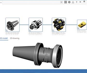
Adveon for example, was developed by Sandvik Coromant as an open tool library for CAM software and other uses. Because the platform is open, a user is able to work with cutting tool data sets from various suppliers, assuming, of course, that the data conforms to ISO 13399 and is linkable to the platform. After launching Adveon, the user has the option to select the available tool catalogs from which the software will search and download cutting tool data. The GTC provides the classification framework to support a variety of search functions.
From the search results, the user can download the choice of tooling item and associated files. Thanks to the GTC specifications, these files and data will be appear in a uniform format and have a similar appearance, regardless of the catalog being sourced. The downloaded data is stored in “My Items,” the area in which the user builds a library of tooling items from which tool assemblies can be created. The user creates, stores and maintains existing tool assemblies as complete digital models in the “My Assemblies” area.
Models of cutting tool assemblies can be used to populate the tool libraries in CAM systems that provide a tool library feature or module in their software. Using models from an open-platform application will be simpler, faster and more reliable than manual options. For machine shops that have several CAM systems with a tool library, downloading tooling data to these additional systems may also be possible. Ideally, the shop can use an open-platform tool library such as Adveon to maintain a master list of available tooling assemblies for all of its NC programming requirements, rather than building and maintaining separate libraries in each CAM system.
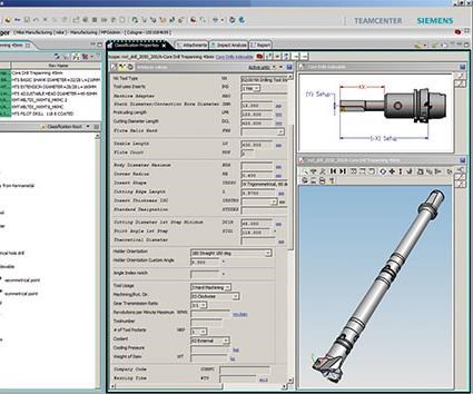
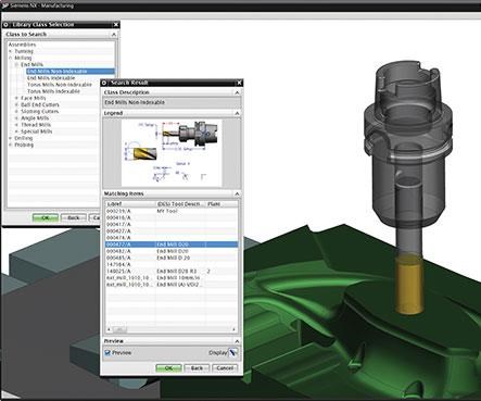
Siemens PLM’s Manufacturing Resource Library (MRL) is likewise able to read ISO 13399/GTC catalog data, select the tool components using a guided component search process and create tool assemblies, which include a 3D assembly model representation. Because MRL can include several cutting tool vendor catalogs, the user may mix and match components from different vendors in the same tool assembly. MRL is integrated with NX CAM, so users of this software can select tool assemblies for accurate toolpath generation and collision detection while using their regular NX user interface. Users may also utilize the tool assembly to create tool setup sheets and bills of materials in NX. NX CAM access to MRL tool assemblies can be done over the cloud, which enables sharing the same tool assembly library among several sites.
Kennametal also believes that customers should be able to have access to tooling data in the software of their choice. In order to access essential cutting tool information within the design and manufacturing processes, Kennametal is providing customers with product catalogs in the GTC format. Novo, the company’s tool advisor and management application, supports the creation of such catalogs that can be imported into Siemens’ MRL software, for example. Moving ahead with the GTC helps the manufacturing community by integrating Kennametal’s tooling information in the end-to-end product development processes, a company spokesman says.
Greater User Demand Is Needed
In concept, the completeness, accuracy and validity (“up-to-dateness”) of tooling assemblies derived from open-platform tool library systems have numerous benefits. For example, downloading 3D models will improve the results of machining simulation and process optimization in CAM. These libraries will certainly encourage greater use of advanced programming capabilities. Likewise, the 2D drawings can easily and quickly be incorporated in tooling setup sheets and other digital documents flowing across shop networks in a paperless environment.
It is also important to note that developers of these open-platform tool libraries have strategies for including speed and feed recommendations as part of the data that will be available from the digital cutting tool catalogs. Needless to say, this is a complex and sensitive area that bears watching because of the promises it implies.
To be clear, our industry is still in the early stages of these developments. The business models by which the tooling libraries and the underlying tool catalogs will be available are still in formation. Adveon, for example, is available from CAM suppliers as a stand-alone software application on a subscription basis. Several CAM software developers are offering it as an add-on to their CAM systems, while others are integrating it as the built-in tool library module for their software. It is best to consult with your cutting tool suppliers and CAM providers for what is currently available and on what basis. Also keep in mind that ISO 13399/GTC data is not yet available from every cutting tool manufacturer. Growing demand from customers, however, will promote wider adoption of these data exchange formats and enhance the usefulness of the open-platform libraries and applications that build on them.
Shared Experiences
Let’s return one more time to the experience of searching for and finding a certain book. It’s that science fiction classic you enjoyed as a young teenager. Rereading it decades later, maybe you’d like to know what other adults thought about the book when they returned to it, too. An online search turns up a forum in which hundreds of people in your generation who rediscovered this book have rated it on numerous characteristics. You are glad to see that most of them still gave the book good reviews. You might pick up some good recommendations for further reading, or connect with like-minded readers on social media.
This experience is not unlike what lies ahead for professionals in manufacturing. In the world of metalworking, for example, we have entered a new era in which the ability to connect machine tools and other equipment to a Web-based network and derive substantial value from these connections is more practical and compelling than ever.
Critical data about the performance of cutting tools in machining process will be generated in new ways by sensors and feedback devices using a variety of digital media. As we have seen, complying with data exchange initiatives such as ISO 13399 and the GTC will ensure compatibility and exchangeability of data formats. In turn, network connections will enable software applications to gather, record, analyze and react to this data, ultimately leading to better decisions about how cutting tools are selected and deployed.
The result will push cutting tools and the overall machining processes to an optimal level of performance. For example, machining parameters such as cutting speeds and feeds will reflect the settings most effective, as proven by operator experience, cutting tool manufacturer, machine builder and the online community of end users. Real-time updates to the machine settings will be applied immediately and automatically to maximize productivity, minimize energy consumption and promote safety. Tool library and toolpath options for programmers will be updated accordingly as well.
The Industrial IoT creates a dynamic new context in which work (done by both humans and machines) will be carried out. Shared experiences and shared results will infuse this context and expand the possibilities for transforming raw materials into desirable goods. The connected workplace will exist within a connected world space, as well. Can we dare think of this as one big book club perhaps?
Related Content
Automated CAM Programming – Is Your Software Really Delivering?
A look at the latest automation tools in Autodesk Fusion 360 software and how forward-thinking machine shops and manufacturing departments are using them to slash delivery times and win more business.
Read MoreCutting Part Programming Times Through AI
CAM Assist cuts repetition from part programming — early users say it cuts tribal knowledge and could be a useful tool for training new programmers.
Read MoreContinuous Improvement and New Functionality Are the Name of the Game
Mastercam 2025 incorporates big advancements and small — all based on customer feedback and the company’s commitment to keeping its signature product best in class.
Read MoreOrthopedic Event Discusses Manufacturing Strategies
At the seminar, representatives from multiple companies discussed strategies for making orthopedic devices accurately and efficiently.
Read MoreRead Next
ISO 13399—A Key Step Toward Data-Driven Manufacturing
Decisions about the cutting tools used in machining operations are arguably among the most important in modern manufacturing.
Read MoreRegistration Now Open for the Precision Machining Technology Show (PMTS) 2025
The precision machining industry’s premier event returns to Cleveland, OH, April 1-3.
Read MoreBuilding Out a Foundation for Student Machinists
Autodesk and Haas have teamed up to produce an introductory course for students that covers the basics of CAD, CAM and CNC while providing them with a portfolio part.
Read More




.jpg;maxWidth=300;quality=90)


.jpg;maxWidth=300;quality=90)
