Sourcing Automation
A new kind of 'automation project manager' helped this company install a roboticized machining cell, the first of several now operating in its plant.
Share


Takumi USA
Featured Content
View More


Hwacheon Machinery America, Inc.
Featured Content
View More


ECi Software Solutions, Inc.
Featured Content
View MoreA plain wooden pallet, its slats weather-beaten and gray, glides silently forward, empty. As it moves across the rollered conveyor, it passes underneath a steel track about 3 feet off the ground. The pallet noiselessly comes to rest on the other side of the raised track.
This seemingly unremarkable scene is, in fact, very remarkable.
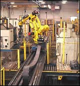
To witness it, you’ll have to travel all the way to Oskaloosa, Iowa, a community of 11,000 in the center of a state filled mostly with fertile fields growing corn or soy beans. Find the Clow Valve Co. plant about a half a mile from the castle-like county courthouse in the center of town. When you get to the plant, depending on your timing, the remarkably unremarkable pallet will be receiving a cast iron valve body fully machined on one of four CNC machining centers nearby. The valve body will be deposited on the pallet by an articulated arm robot that moves from machine to machine on the elevated track, loading and unloading whichever machine has signaled its readiness.
When the wooden pallet is neatly filled with three, four or five rows of finished valve bodies, the conveyor system will automatically move the pallet to another rollered conveyor running at right angles and carrying the valve bodies to the paint line. In the meantime, another wooden pallet filled with unmachined valve bodies will have rolled into place on the other side of the elevated track, where the robot can reach the pallet there as well. Behind this filled pallet on the conveyor are still more pallets, each carrying from six to 20 valve bodies. Each of these workpieces is in the spot on the pallet where it was placed at the foundry, the last time human hands touched it. (Human hands will not touch these parts again until they are hung on hooks to enter the washer and powder-coating system.) This quiet parade of filled, then unfilled, then refilled pallets will continue all day, all night, all week and all year, as it has since June 2000.
Simpler Castings, More Machining
That automation is the key to reducing the role of labor in any manufacturing process is now widely recognized. The four-machine robotic cell at Clow Valve in Oskaloosa is a perfect example of this principle. However, the cell is also a perfect example of several other principles about automation that are not as well recognized.
- Effective automation on this scale can be difficult to achieve. The technical issues are challenging, although the solutions may be decidedly low-tech.
- The sources for automated systems are changing. A new breed of “automation project manager” is emerging to make automation more accessible to companies that would otherwise be unable to develop effective automated systems on their own.
- Automation is rarely perfect as originally installed. Because each application is unique, unforeseen difficulties or opportunities for enhancement may not appear until after the system is up and running.
Clow Valve caught on to the importance of automation many years ago. Since the early 1990s, the necessity to increase both throughput and output without adding to the labor force arose from growing demands in the marketplace for better products at lower prices. However, a more fundamental motivation was also at work here. (See box at right.)
Clow Valve is a leading national supplier of products for water distribution, water and wastewater treatment and fire protection systems. There’s a good chance that the fire hydrant in front of your workplace or residence was produced by Clow or by one of its sister companies in the McWane family, Kennedy Valve of Elmira, New York, M & H Valve in Anniston, Alabama, or Clow Canada in St. John, New Brunswick.
Clow Valve adheres to the specifications and recommendations of the American Water Works Association (AWWA), the national membership organization that represents the needs and interests of municipal water works and fire departments. In fact, the automated cell to which the plain wooden pallet has drawn our attention was originally inspired by a standard issued by the AWWA about 5 years ago. The new standard now allowed gray cast iron or ductile iron for the kind of valve bodies being produced at Clow Valve in Oskaloosa. Called non-rising stem (NRS) valves for the way a threaded rod-like stem opens and closes the internal waterway to control the flow of water in a pipeline, these valves are used in virtually every municipal water supply, irrigation system and water treatment plant.
“The addition of ductile iron gave us a chance to reconsider the design of the valve bodies as well as how we manufacture them,” explains Rick Bryan, machine shop manager. The gray iron parts were originally designed to cast in as many features as possible, minimizing the amount of machining required. The opposite strategy was decided on for the redesigned valve. “Clow Valve has its own foundry on the other side of Oskaloosa. By maximizing the amount of machining to produce the full range of valve bodies, we could minimize the number of different cores required to make the whole family,” Mr. Bryan says.
This approach had several other advantages: It greatly reduced the number of new cores for the foundry while dramatically reducing the cleaning and grinding required, tasks which are very ergonomically challenging. It simplified foundry production schedules and reduced in-process inventory. Most important, it allowed key features to be machined rather than as-cast to produce higher quality parts. For example, machining the elliptical groove for a critical O-ring seal was clearly superior to the as-cast groove on the original gray iron.
“This was a great strategy,” Mr. Bryan remarks, “but now the challenge was how to handle the additional machining required so that these parts would be no more expensive to produce with machined features than with as-cast features.” Automation was the clear choice to create the added capacity without adding new labor and thus maintain the cost advantage.
Getting Automation Is Not Automatic
But what automation? At first, the company considered large rotary transfer machines but was concerned about the complexity of these machines and about their flexibility. One of Clow Valve’s local machine tool distributors, Ellison Machine Tools & Robotics/Iowa Division, had another suggestion.
Brad Woody, the key account manager from Ellison in Davenport, arranged for Rick Bryan and a team from the plant to visit a customer near Chicago. There, the Clow Valve team inspected a flexible machining cell built around standard CNC HMCs from Okuma and a Fanuc articulated arm robot to load and unload the machines. At the time, Clow Valve was introduced to Meritage Manufacturing Solutions (MMS) as a new organization for sourcing automation. (See box to right.)
The merits of a similar robotic cell for the NRS valve bodies won the Clow Valve team over to this approach. “And that’s all we had at that point—an approach, a concept,” Mr. Bryan recalls. It would be 2 years of planning, preparation and construction before the line began operation. “This is where working with Meritage and its partners really paid off,” Mr. Bryan says. “We had one source providing and coordinating the engineering, the machines and electronics and taking responsibility for the effectiveness of the cell.” Mr. Bryan makes it clear, however, that Clow Valve had to do its part.
To further heighten the challenge, Clow’s sister companies in New York and Alabama had decided to install nearly identical cells in their own facilities to produce NRS valve bodies, so teams from these companies were involved in all of the planning and preparation stages as well. Ultimately, the cells installed at each facility were somewhat different because conditions at each location were not the same. Discussing the cell at Clow Valve in Oskaloosa, however, covers all of the ingenuity and innovation represented in each of the cells.
“One of the most important lessons we learned is that thorough up-front planning and engineering pays off,” says Mike Hildenbrand, plant general foreman. “The entire team has to be clear about goals and expectations, then work out all the details. You have to be patient and persistent.”
Seeing-Eye Grippers And Other Good Stuff
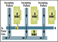
The finished cell is diagrammed in Figure 1. To understand what a technical accomplishment this line represents, it is only necessary to look at several critical features that contribute to the cell’s success. These include the robot gripper, the workholding fixtures and the pallet system.
Mr. Hildenbrand admits that without expert help from the outside, he doubts that his shop would have been able to achieve the same level of efficiency with the machining line. “Few companies like ours have the wide range of experience and know-how to tackle automation on their own, but working with Meritage was not like working with outsiders,” Mr. Hildenbrand says. “They got to know our product and processes intimately—as well as we did. That kind of close working relationship between their team and the Clow team made the system much more effective and successful.” Mr. Hildenbrand believes that this is evident in the engineering solutions that characterize the line.
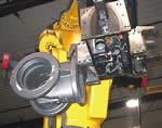
The robot gripper, for example, was designed and manufactured by Automated Concepts, Inc. (Council Bluffs, Iowa) under the direction of MMS. Although Clow Valve produces seven different sizes of NRS valve bodies, the robot gripper handles valve bodies in any of these sizes, which range from the 2-inch version that weighs about 10 lbs to the 12-inch version that weighs 190 lbs. Likewise, the gripper has to locate incoming castings as they were found resting on the plain wooden pallet. The gripper has to provide positive feedback that the valve body was securely and safely in its grasp before being transferred.
According to John Burg, who headed up the design and engineering effort, the “secret” to the gripper design is an integrated vision system developed by Fanuc Robotics. (See Figure 2.) Essentially, a digital camera is mounted inside the gripper body, giving it a set of “eyes” to locate an incoming valve body on the pallet. The camera takes a “snapshot” of the valve body and transmits the image to the vision system controller. There, the coordinates of one prominent feature found on every size valve body are used to orient the robot’s pick and place routine. This approach automatically compensates for the variations in valve placement on the pallet. Foundry hands simply have to get the valve bodies upright and facing the right direction on the pallet.
“The line does not need manual load and unload stations. That’s a significant labor savings compared to other system designs,” says Mr. Burg. “It also lets us get by without costly T-slotted pallets and multiple redundant workholding fixtures for delivering parts to the machining centers.” According to Mr. Burg, these benefits contrast sharply with the fixed-rail, pallet-shuttle design of many existing flexible machining systems (FMSs).
The robot gripper features an unusual, three-sided design, with a set of hydraulic gripping fingers on each side as well as on the front. The opposed fingers act like the thumb and the first two fingers on the human hand to grasp the valve body from the inside and outside of the neck. When proximity sensors located in the gripper are activated, they send signals to the robot controller that the valve is properly seated. Otherwise, the robot will not proceed and an alarm condition stops operation.
Generally, the gripper operates in a two-sided mode whereby the robot uses the empty side of the gripper to retrieve the finished part, then rotates and loads an unfinished part into the machine’s modular clamping system. The robot then takes the finished part and deposits it on a pallet before getting another unfinished valve to repeat the sequence.
However, for the larger and heavier 10- and 12-inch valve bodies, the gripper is used to handle only one part at a time, using the front set of fingers. Machining cycle time for these larger valves is long enough for the robot to keep up by depositing the finished valve body before it goes back to pick up a blank and bring it back to the waiting fixture on the machine.
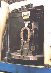
The workholding fixtures on the machining centers are another key to the line’s success. The three HMCs are all equipped with a modular fixturing system using common baseplates permanently mounted on the rotating pallet system in each machine. See Figure 3.
Sets of interchangeable components allow the fixtures to be switched from one size valve body to another in about 20 minutes. Various sizes of uprights accommodate the different diameters of the valve bodies, while a hydraulically actuated top clamp, also interchangeable and sized to match the part dimensions, raises and lowers to secure the valve body in the fixture. The electronic control system for the cell coordinates the sequence of clamping and unclamping events when a workpiece is ready to be unloaded.
An entirely different approach to workholding was applied to the one vertical machine in the line. All eight sizes of valve bodies can be ordered with an optional tapped hole for inserting the stem of a pressure gauge in the end product. The main duty of the VMC is to produce this hole in designated valve bodies.
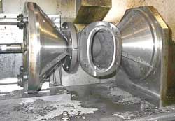
Because only a small percent of the NRS valve bodies are delivered with this hole, it was important to keep fixturing and tooling for this operation as simple and economical as possible. Here’s what the team came up with, as shown in Figure 4. A universal clamping fixture accepts all sizes of valve bodies by means of two cone-shaped components. One cone is fixed; the other is retractable. The cones achieve the same level of contact and clamping force regardless of the size of the waterway opening.
The pallet conveyor system developed for the line met several challenges. Perhaps the most important is using the factory’s wooden pallets. Clow Valve uses hundreds of 42- by 48-inch wooden pallets throughout its plants in Oskaloosa. They are sturdy, easy to maintain and easy to dispose of when spoiled.
“Putting the robot on an elevated track so that the pallets can simply pass underneath proved to be a great idea,” says Mr. Burg. “The robot track could be kept in straight line, and the robot works equally well elevated as it does from a floor mounted system.” Raising the track posed no engineering difficulties and did not add significantly to cost, he explains.
The control system for the pallet conveyor, however, is not unsophisticated. All pallet movements are coordinated by programmable logic controllers that are interfaced to the master cell controller. This prevents collisions when pallets are moved to the outbound conveyor for transfer to the paint line.
Running The Cell
Grippers, fixtures and pallets may explain how the cell works, but they only hint at how the cell runs. According to Ron VanPolen, cell supervisor, two things keep the cell running: the computerized control system and one operator per 8-hour shift. Each has essential duties.
The control system was also engineered and designed by Automated Concepts working closely with the factory teams and Meritage Manufacturing Solutions. Clow Valve produces the NRS valve bodies in lots to maintain inventory levels based on sales predictions. The production schedule determines the workload for the cell and indicates when changeovers will have to be performed to accommodate the sizes of incoming valve bodies. “This changeover occurs once every other day or so. Typically the cell will be set up to handle two or three valve sizes, which may be the smallest on one machine and the largest on another,” says Mr. VanPolen.
The operator on duty monitors the cell’s performance, responds to alarm signals, changes over the clamping fixtures, makes sure chip barrels do not overflow and replenishes perishable tooling. All of the machines are stocked with redundant tooling so that cutting tools can be replenished without interrupting cell operation. The operator can access the tooling magazines from the rear of the machines. To change over the clamping fixtures, the operator must enter the cell to access the front of the machines.
The HMCs on either end can be taken off line for the switchover while the other two machines continue to operate. The middle machine, however, requires light curtain protection to prevent the robot from passing when the operator is present. This allows the robot to load and unload the two end machines normally in the meantime.
The entire cell, of course, is fenced and gated with safety interlocks. Safety was forefront throughout the planning and engineering stages. As Mr. VanPolen points out, the line must run around the clock but with a perfect safety record. “One of the important benefits of automation is increased safety. With a robot doing all of the heavy lifting, there are fewer chances for accidents and repetitive motion injuries,” he says.
Automation in the flow
After the cell was installed, the effort to make it more productive and efficient continued. The teamwork between Clow Valve and Meritage also continued. The goal has been to improve reliability and uptime, not to achieve maximum speeds and feeds, although cycle times have dropped significantly due to the application of CNC for all machining operations.
Continued involvement of an automation project manager after installation has proven to be a major value to the company, says Mr. Bryan. “There were some surprises that required their expertise to resolve.” For example, the vision system on the robot required a steadier, stronger source of light to function reliably. Solving the problem involved covering skylights and adding new overhead lamp fixtures optimally placed to minimize shadows.
Cutting tools and their feeds and speeds have also been adjusted for improved results.
A true test of the cell’s flexibility came when Clow Valve found that market acceptance of the ductile iron valves was not as rapid as expected. This meant modifying the gray cast iron valve bodies so they too could be machined on the cell. Only slight modifications had to be made to the cell itself. Grippers and clamping fixtures could accommodate the gray cast iron valve bodies. Writing new machining programs was the biggest challenge.
The NRS valve body cell was to be the first of four robotic cells installed at the plant, all of them designed and engineered by MMS as integrator. More of them are on the way.
“Now that we have these cells up and running successfully,” says Mr. Bryan, “we’re discovering lots of opportunities for automation throughout the shop.”
Related Content
Fryer’s Horizontal Boring Mill Designed for Ease of Use
The HB Series Boring Mills feature rugged cast iron bodies and high-precision ballscrews and bearings to ensure high-accuracy tolerances.
Read MoreShop Replaces Two Verticals With One Horizontal
By trading two VMCs in to help finance the purchase of a new HMC, this shop was able to significantly increase production and move to lights-out machining.
Read MoreDN Solutions America Unveils Impressive Chicago Technical Center at IMTS 2024
New tech center is serving as a cutting-edge showroom and a technological hub for advanced machining applications.
Read MoreFryer Offers Compact HMC for Small-Lot Machining
The Fryer HR-40 features a built-in 24" rotary table for multi-sided machining.
Read MoreRead Next
5 Rules of Thumb for Buying CNC Machine Tools
Use these tips to carefully plan your machine tool purchases and to avoid regretting your decision later.
Read MoreBuilding Out a Foundation for Student Machinists
Autodesk and Haas have teamed up to produce an introductory course for students that covers the basics of CAD, CAM and CNC while providing them with a portfolio part.
Read MoreRegistration Now Open for the Precision Machining Technology Show (PMTS) 2025
The precision machining industry’s premier event returns to Cleveland, OH, April 1-3.
Read More




.jpg;maxWidth=300;quality=90)


