
Simulation Speeds Cycle Times On Complex Parts
Selecting "safe" feed rates resulted in wasted time or poor cutting conditions on complex fuel-control parts. With optimization software, this shop achieved more aggressive feed rates.
Share


To elimate chatter and improve surface finishes, the company uses Vericut's OptiPath module to determine the appropriate feed rates.
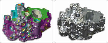
Comparing the design model to the Vericut “as machined” model helps Tell Tool locate gouges.
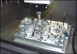
Tell Tool of Westfield, Massachusetts, is a shop that produces electronic engine controls and other system components for aircraft. Taking advantage of Vericut CNC simulation and optimization software from CGTech (Irvine, California), the company makes fuel-control units much differently today than it did just a few years ago. The software helps programmers arrive at more efficient tool paths and cutting conditions so the shop can use its machining centers more efficiently.
In the past, Tell Tool was forced to rely on casting to produce the complex fuel-control units. Now, the company can create a complex part from a solid block of material. Tell Tool’s vice president of engineering, Robert Morin, recently explained the process: “Basically, what we do is create what would have been a casting in the old days. Because we can use blocks of material, there’s much better integrity than a casting. In casting you tend to get a lot of porosity and leakage. Now, with the advances in technology in the last decade and a half, we’re able to get away from castings on the newer products.” However, he says, “The part programs are extremely long. That’s what drove us to look at Vericut in the early 1990s. Back then, the software did not support what we needed to do because our models were so large and complex. But over the years, CGTech has made a lot of changes for us.”


When a customer contracts Tell Tool for a fuel-control unit, there is often no design model of the final part shape. The company usually receives specifications only for the dimensions of the inside of the part, minimum wall thicknesses and specific structure requirements, along with some other information.
To create the outer shape, Tell Tool reverse-engineers the unit from the inside out using internal-part specifications such as fuel-control-housing dimensions and the minimum wrap-stock requirements around each feature. “Basically, we take a block of material, and we have a model from our customer that we import into Vericut,” Mr. Morin says. “We use CAM software to create the cutter path. We then import that program into Vericut and run it over the part.”
Senior Programmer Charlie Diemer explains further, adding, “We start out with a full block of aluminum, maybe 8 by 10 by 12 inches, and in that we’re going to cut 20 to 30 percent of the outside to create the first operation. After running this operation in Vericut, we will make an STL model of the remaining stock to import into the CAM software as a stock model. We use the software’s Model Export to output an STL after each operation so the programmers know exactly what the part will look like when they program their next set-up. At each operation we’re creating a new stock model for each subsequent operation.”
Prior to implementing Vericut, programmers approximated the shape of the in-process material and ran the cutter path within those imaginary boundaries. As a result, there were a lot of air cuts in which the cutter did not contact material.
Determining optimum feed rates has traditionally presented NC programmers and machinists with a number of problems as well. Typically, the selected feed rate represents a compromise between tool life, cycle time and the worst-case cutting condition encountered. This “worst-case,” slowest feed rate is ideal for the part at the point where the most material is being removed or the worst cutting conditions are encountered. Unfortunately, this feed rate wastes time and even creates poor cutting conditions everywhere else.
The NC programmers at Tell Tool take a radically different approach now that their programs will be sent to Vericut prior to going to the shop floor. Instead of selecting a slow, “worst-case” feed rate, the programmers select a feed rate that would normally be considered much too fast.
“In the beginning, our programmers start with a very aggressive feed rate. The program will then be run through Vericut’s OptiPath module to generate much more suitable feed rates for the cutting conditions,” says Mr. Grimm. “This eliminates a lot of the chatter, gives us a much better surface finish and helps out with the time is takes to cut the part.”
Mr. Morin adds that as a result of optimizing the NC programs, the shop breaks fewer tools and the part integrity is better. He says, “You don’t have the tool slamming into corners or the tool flexing and putting a lot of chatter in there. You get a better quality product. It’s not as risky. You’re not right on the edge. You can go with a more aggressive feed rate. Because we are using OptiPath, we can let it cut where it can and it will slow it down where it needs to.”
OptiPath works by analyzing either the post-processed NC program (G codes) or the direct CAM system output (CL data). It divides the tool motion into a number of smaller segments determined by user-defined settings in the software. Based on the amount of material removed in each segment, the software assigns the best feed rate. The software then outputs a new NC program, identical to the original one but with improved feed rate settings for each of the segments. It does not alter the toolpath trajectory.
Because of the types of products Tell Tool produces, the “machines never get to their actual feed rate—no matter what you program—because the moves are so short,” Mr. Morin says. “Everything we do, the actual XYZ moves are tenths—two or three tenths at a time—that’s it. It’s real short moves all the time. For us, it’s all about the tool life and surface integrity and finish. We don’t want to be slamming into corners. One thing we found with OptiPath is that it sees when we are going to come into a whole bunch of material all at once, it accommodates the feed rates for what we need—and that’s the biggest thing for us.”
Improved tool life and surface finish are not the only benefits OptiPath provides. “The machines themselves also run a lot smoother.” Mr. Morin adds “You can see it. The types of cuts that we make cause our machines to look as if they are going to dance across the floor. They are accelerating and decelerating constantly. “It would be like driving with your feet on both the brake and accelerator and pumping them both constantly—that’s basically what we are doing to the machine for hours at a time.”
Since there are no dimensions for the outside shapes on the parts that Tell Tool produces, the shop had to find a way for customers to approve the parts.
“We’re using an STL file and Vericut as our final inspection method and that’s accepted by our customers,” Mr. Morin continues. “Once we get the ‘Auto-Diff’ report to zero, they’re satisfied. They sign it off and our cutter path is locked. We can’t change it. Two of our customers have even sent their engineers to CGTech for training to understand the software so that they could buy off on the technology.”
Auto-Diff enables Tell Tool to detect gouges and excess material by comparing the design model to the Vericut “as-machined” model. The design model can be a solid, surface, skin or points. This model is “embedded” inside the rough material for interactive gouge-checking. If the tool contacts the design model, Vericut highlights the gouge and records the error. Different colors can be applied to the design model, rough stock, errors, gouges, collisions or excess material for easy identification.
“On first-piece inspection, we can’t go through and check to anything,” Mr. Morin says. On the complex form machined from solid, there is no dimension to “check to.” As a result, he says, “it’s only checked on the computer.”


Related Content

How to Mitigate Chatter to Boost Machining Rates
There are usually better solutions to chatter than just reducing the feed rate. Through vibration analysis, the chatter problem can be solved, enabling much higher metal removal rates, better quality and longer tool life.
Read More
Continuous Improvement and New Functionality Are the Name of the Game
Mastercam 2025 incorporates big advancements and small — all based on customer feedback and the company’s commitment to keeping its signature product best in class.
Read More
Tips for Designing CNC Programs That Help Operators
The way a G-code program is formatted directly affects the productivity of the CNC people who use them. Design CNC programs that make CNC setup people and operators’ jobs easier.
Read More
Can AI Replace Programmers? Writers Face a Similar Question
The answer is the same in both cases. Artificial intelligence performs sophisticated tasks, but falls short of delivering on the fullness of what the work entails.
Read MoreRead Next

Setting Up the Building Blocks for a Digital Factory
Woodward Inc. spent over a year developing an API to connect machines to its digital factory. Caron Engineering’s MiConnect has cut most of this process while also granting the shop greater access to machine information.
Read More
Registration Now Open for the Precision Machining Technology Show (PMTS) 2025
The precision machining industry’s premier event returns to Cleveland, OH, April 1-3.
Read More
5 Rules of Thumb for Buying CNC Machine Tools
Use these tips to carefully plan your machine tool purchases and to avoid regretting your decision later.
Read More