Rolling Threads Has Advantages
With macros and canned cycles resident in the CNC on most contemporary turning centers, single point turning of OD threads can seem like almost a default process decision. However, for numerous applications, OD thread rolling has inherent advantages as an alternative to cutting threads.
Share


OD thread machining is done primarily with the use of turning—using single point and form tools, and grinding—using single contact or formed wheels. Both of these metalcutting processes are used to remove material to create the desired thread geometry.
Another process available to shops is thread rolling. Thread rolling is not a metal cutting process. It does not remove metal to create the desired profile, but instead it forms the thread into a mirror image of a roller die.
Metalworking manufacturers are under competitive pressures like never before. It’s no longer sufficient to make parts “the way we always have.” Increasingly, matching the best processing technique to a specific application can mean the difference between making money on a job or losing it. Margins are that tight.
To illustrate an alternative to thread turning and grinding, this article looks at the advantages and disadvantages of thread rolling on CNC turning centers. Application specifications and various types of thread rolling are discussed, with technical input from LMT-Fette (Cleveland, Ohio).
Chipless Thread Forming
Generally speaking, materials that are best rolled are difficult to cut and vice versa. Thread rolling relies on the plasticity of the base material—its ability to deform—to permanently imprint the shape of the rolls on the workpiece blank. Good plasticity in a material being cut usually results in a gummy chip formation and built-up edge on the tooling. Cast iron, for example does not have a proper flow characteristic and therefore would not be a candidate for thread rolling.
According to LMT-Fette, because the pressure of the rollers will plastically deform the material, it should have a minimum elongation factor of 5 percent and a maximum tensile yield strength of 246,000 psi. These figures vary with material types and the size of the major and secondary diameters.
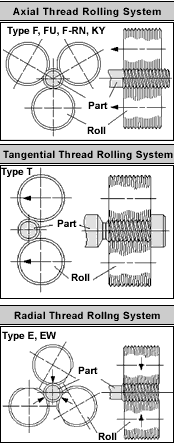
In the thread rolling operation, a head carrying the rollers is presented axially, tangentially or radially to the workpiece. While each type of roller head operates on the same basic principle, different threading applications require different approaches to the workpiece blank. Details of the three thread rolling types are discussed later in this article.
Assuming the workpiece material meets the yield and flow requirements for rolling, the process offers several advantages over cutting threads. Compared to other production methods, rolled threads have improved physical properties. The cold working that takes place in the thread rolling process produces an increase in tensile strength and a better surface finish than is achieved with cutting operations.
As in most cold working operations, the metal matrix of the workpiece blank is initially compressed by the force of the die causing it to yield plastically and conform to the shape of the die. Thread rolling operates in much the same way. The form of the roller or rollers in the thread rolling head imparts the shape of the thread into the workpiece blank.
The compression of the parent material results in a work hardening condition from compressing the metal matrix. It creates fatigue resistance in the thread. This hardened condition is part of the process, so any subsequent heat treating of a rolled thread will have an annealing effect. Thread rolling should be done after heat treating. Turning or grinding on the other hand, whether in a green or hardened state, severs the metal matrix to create the desired shape and leaves the metal grain structure virtually intact.
Material Rollability
Successful thread rolling is a function of several application parameters. Among them is the type of thread to be rolled, its major diameter, pitch and root depth. Additional thread rolling considerations involve the ductility and cold-flow properties of the blank material.
When a thread is rolled, the thread shape is imparted on the workpiece blank by moving the parent material. A key parameter of this movement is the depth or root of the thread. As the roller displaces the material that will become the root, it flows out of the root both radially and axially.
The position of the rollers holds the thread pitch diameter to a predetermined size so the displaced material actually lengthens the workpiece blank. Depending on the size and shape of the thread being rolled, material savings of 15 to 20 percent can be realized using thread rolling over turning or cutting. On a large production run, this can add up to a significant amount of stock.
Because of the close relationship between the outside diameter of the thread and the workpiece blank, it is critical that blank diameters be highly accurate. The material flow rate is calculated based on the specified blank diameter and variation. Either over or under this diameter will produce unacceptable threads.
Undersized material will not fully flow into the roller dies and will cause undersized threads. Oversized blanks will exert undue pressure on the rollers and head resulting in potential damage to the thread rolling unit.
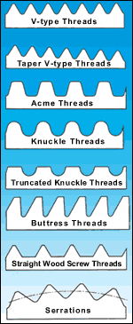
Thread rolling success is determined in large part by the shape of the form to be produced. Most of the threads produced are made to the 60 degree Unified and similar standards, which are easily rolled. Most of the rollers used to produce these forms have relatively sharp crests, usually with radius edge to help the die penetrate the material. The angles of these threads, 30 degrees on each flank, provide the force to make the material flow axially and radially in a controlled and predictable manner.
Acme and worm threads can be rolled, but the relatively large amount of material displacement and the distance the material must move can cause flaking on the flanks. Rollability of these types of threads is improved by changing the thread’s root configuration from flat bottom to a radius. Thread rolling can also be applied to burnishing, knurling and, in some cases, swaging operations.
Axial Thread Rolling
Depending on the type of machine and thread that needs to be manufactured, shops have several thread rolling configurations from which to choose. An axial thread roller moves from the tailstock end of the turning center, along the workpiece blank centerline, to create a thread. General working ranges for axial heads are from 0.06 to 9 inches in diameter.
The axial head is usually mounted in one of the turning center’s turret tool pockets. In one pass, three (or up to six) rollers are fed onto the blank and activated by the rotation of the workpiece blank.
The arrangement of the rollers on an axial head allows the blank to pass through, which enables threads that are longer than the roller width to be formed. The first few threads on these heads are progressive, like a tap or broach, and require a chamfer on the workpiece blank. Shorter progressions can be used for work up to shoulders or other workpiece features, but roller life can be affected by the additional stress.
Tangential Thread Rolling
As the name implies, the tangential roller head makes its threads by approaching the workpiece blank from the side. Sometimes called side rolling or cross slide heads, tangential thread roller are designed to roll threads by pushing, at a controlled feed rate, two fixed parallel rolls onto the rotating component. Mechanical or servo feed is required for tangential thread rolling. It is not possible to operate these rollers manually.
The rolls make square, tangential contact with the workpiece blank diameter forcing the material to plastically flow uniformly, taking the shape of the roller dies. This forming process is very fast and produces a precision profile, which is burr free.
In operation, the tangential roller will produce a complete thread in 15 to 30 revolutions of the workpiece blank. An advantage of this thread roller type is it can form threads very close (within one thread or sometimes less) to either the front or back of a shoulder or other workpiece feature.
Tangential rollers only roll threads within the width of the rollers. Working width ranges for Fette’s tangential rolls are from 0.61 to 1.59 inches. These rollers are not recommended for Acme and trapezoid threads because force required is beyond the design limits of the holders.
Radial Thread Rolling
A third type of thread roller is the radial head. It uses two or three rolls to form a thread in a single rotation of the workpiece blank.
The rolls on this type of thread roller are ground eccentrically. Starting with a flat on each roll, the thread form is progressive. A shallow thread form starts at one side of the flat and full form at the other side.
A three roll radial head at rest uses the aligned flats to create a clearance opening. This allows the workpiece blank to be positioned between the rolls and the finished threaded part to exit without damage to the threads. The two roll head uses the same principle.
Internally, the rolls are set in motion by releasing tension springs attached to a rotating clutch. Once released, the rotation of the workpiece or the roller unit continues the forward motion of the eccentric rolls until the torque of the workpiece blank resets the clutch spring.
The working range for the radial thread rolling head is 1/16 to 2 ½ inches in diameter. Like the tangential head, the thread length cannot exceed the width of the thread rollers.
It’s About Flexibility
Accurate and precise machining of threads is a key skill set for any shop. Considering thread rolling as a potential tool for the manufacture of threaded parts should be among a shop’s processing strategies.
Thread rolling requires a tooling investment to be made in the heads and rollers, which is higher than a single-point threading insert. However, for applications that involve hardened material, high surface finish and surface integrity as wells as production volumes, thread rolling technology may be more cost effective over the long haul. Moreover, since the heads can be run on a CNC turning center alongside single point threading, thread rolling can be flexibly applied as needed by the application—the right tool for the job.
Related Content
Orthopedic Event Discusses Manufacturing Strategies
At the seminar, representatives from multiple companies discussed strategies for making orthopedic devices accurately and efficiently.
Read MoreHigh RPM Spindles: 5 Advantages for 5-axis CNC Machines
Explore five crucial ways equipping 5-axis CNC machines with Air Turbine Spindles® can achieve the speeds necessary to overcome manufacturing challenges.
Read MoreQuick-Change Tool Heads Reduce Setup on Swiss-Type Turning Centers
This new quick-change tooling system enables shops to get more production from their Swiss turning centers through reduced tool setup time and matches the performance of a solid tool.
Read MoreThe Future of High Feed Milling in Modern Manufacturing
Achieve higher metal removal rates and enhanced predictability with ISCAR’s advanced high-feed milling tools — optimized for today’s competitive global market.
Read MoreRead Next
Setting Up the Building Blocks for a Digital Factory
Woodward Inc. spent over a year developing an API to connect machines to its digital factory. Caron Engineering’s MiConnect has cut most of this process while also granting the shop greater access to machine information.
Read MoreRegistration Now Open for the Precision Machining Technology Show (PMTS) 2025
The precision machining industry’s premier event returns to Cleveland, OH, April 1-3.
Read More


.png;maxWidth=300;quality=90)


