
QFS Keeps Its Customers Moving With Integrated CAD/CAM
Quickly updating tool paths to remachine die surfaces enables this shop to provide short runs of prototype formed sheet metal parts. This fast response to engineering changes and design adjustments helps its customers adhere to tightly scheduled vehicle launch programs. QFS relies on integrated CAD and CAM software to make this happen. In this case, the software of choice are PowerShape and PowerMill from Delcam.

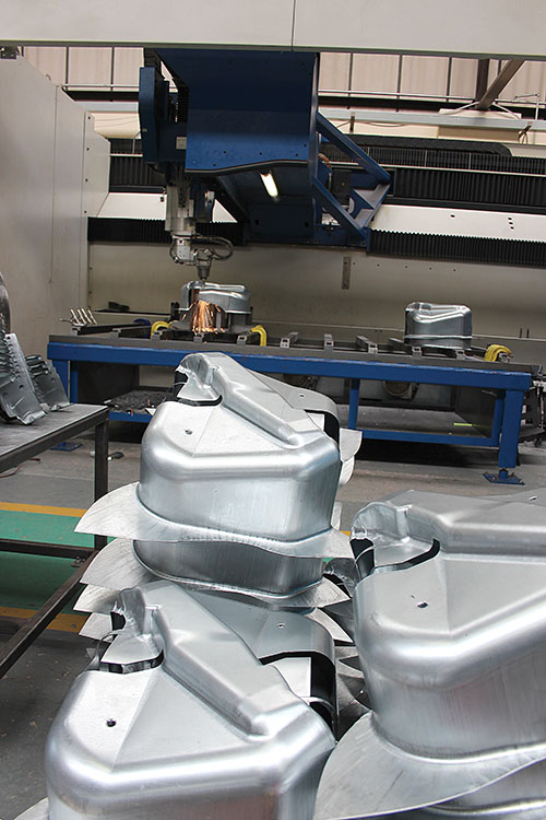
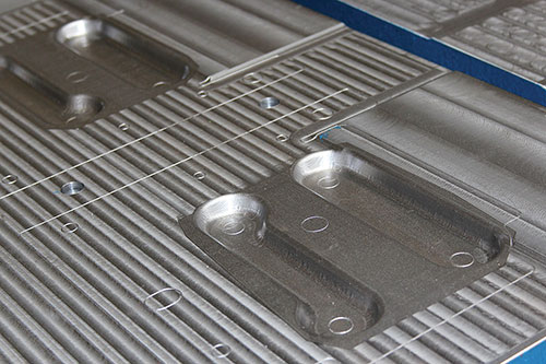
Producing prototype sheet metal parts made in low volumes is one of QFS’ specialties.
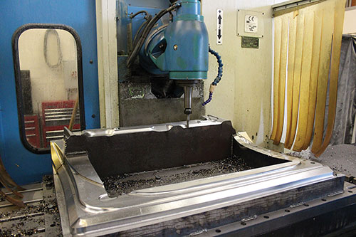
Large die components are produced on the shop’s multi-axis CNC milling machines. QFS uses Delcam’s PowerMill for its multi-axis programming capability.
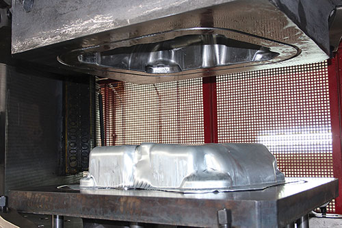
Completed die sets like the one to the left are rushed to the press department.
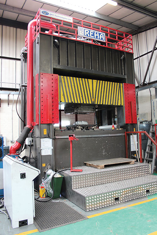
Presses as large as 250-ton capacity produce components in completed die sets for testing and evaluation.
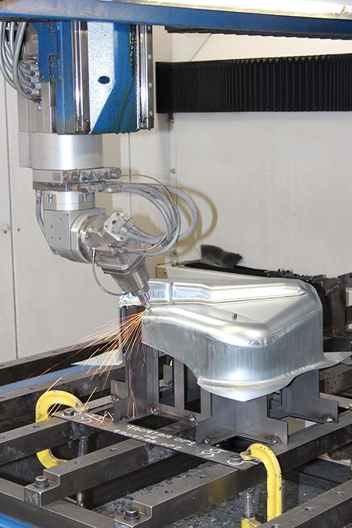
Formed workpieces can be trimmed on a five-axis laser cutting machine, which can also make openings that represent piercings of various shapes.
Die work involving the machining of fine details is also programmed with PowerMill.
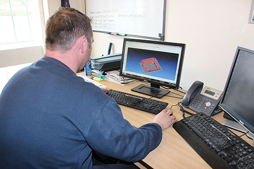
Tony Goodwill, CNC programmer and machinist, checks revised die geometry in PowerShape.
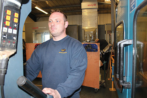
On the shop floor, PowerMill enables him to quickly create and edit tool paths for machining new die surfaces.
Share


Takumi USA
Featured Content
View More


Hwacheon Machinery America, Inc.
Featured Content
View More


One of the many things that QFS Technologies Ltd., a prototype shop in Birmingham, UK, does well is generate small batches of die-formed sheet metal parts that virtually match their production-run counterparts. This service enables QFS’s customers in the automotive sector to quickly test and evaluate component design. This is an interactive, back-and-forth process. The shape of the formed part may undergo several revisions and engineering changes as the automaker moves aggressively to launch a new car, truck or SUV.
It’s up to QFS to keep up by supplying updated versions of the part in short order. For this company, a critical capability is re-machining press die surfaces to reflect the latest revisions from the customer. This means quickly analyzing new geometry from design engineers and generating appropriate toolpath data for the multi-axis CNC machining centers that will do the work.


QFS relies on integrated CAD and CAM software to make this happen. In this case, the software of choice are PowerShape and PowerMill from Delcam, whose world headquarters are located on the other side of this sprawling UK city. The integration of this CAD and CAM software helps streamline the vital reprogramming process.
It’s routine for the company to get the revised parts out the door in a week or 10 days. The same combination of CAD and CAM software also enables QFS to manufacture the original short-run dies in about four weeks. With QFS as one of their best prototype partners, some of the biggest names in that UK auto industry, including Jaguar, Land Rover and Aston Martin, are bringing vehicles with bold, market-leading styles to showrooms around the world in record time.
A Model Shop
Although QFS strives to be a company with exceptional, even unique, capabilities, it is also broadly emblematic of many other shops and specialty machining companies in that country. Like QFS, their emergence reflects the strong revival of manufacturing in the UK. Once given up for dead by many of its pundits, manufacturing is clearly on the rebound there. Led by a resurgence in the aerospace and automotive sectors, this revival has inspired a new generation of small- and medium-sized manufacturing companies that are, by necessity, highly dependent on multi-axis CNC machine tools, strong CAD/CAM support, and lean, nimble operations. QFS certainly fits this model.
Founded with five employees in 1997, the prototype shop can’t be called a startup. However, its “growth spurt” in recent years is a response to the needs of its thriving customers. These include not only vehicle manufacturers, but also well-known names in aerospace (such as GKN and Rolls Royce) and railcars (such as Thyssen-Krupp). The company now has around 30 employees and occupies five spacious units in a suburban industrial park on the outskirts of Birmingham. (Plans to relocate and consolidate these facilities under one roof are currently in the discussion phase.)
In addition to two three-axis machining centers and a five-axis gantry mill, the company has several two-axis and five-axis laser cutting machines, plus a half dozen hydraulic and mechanical presses ranging to 250-ton capacity. A variety of welding, measuring and scanning equipment rounds out its equipment list. In short, QFS has all it needs on site to start with sheets of steel or aluminum, and deliver complete automotive body panels, subassemblies and press-formed components. These are provided as prototypes or as short-run production pieces that fill the gap while high-volume production tooling is completed.
Prototype Production
A typical press-formed prototype might follow this path: QFS accepts a digital file of the part geometry or, in some cases, starts with paper prints—whatever the customer has at the ready. Design engineers working in Catia and AutoForm create and refine the part model and press dies to form it. To substitute for complex trimming dies or piercing tools, laser cutters are programmed to do these operations instead.
To machine the press die surfaces, the CAD models are turned over to the CNC department, where geometry is oriented in PowerShape to best suit the configuration of the machining centers. For example, the five-axis Correa Anayak gantry mill is generally operated in the 3 + 2 mode, so choosing the best workplanes is important.
Switching over to PowerMill, the company prepares the tool paths for machining blocks of aluminum or Obomodulan (a dense but resilient polyurethane material that is ideal for short-run dies). QFS has adopted the latest programming features of PowerMill, such as its Vortex high-speed roughing technology, to reduce machining time. Finished dies are then transferred to the forming press of the appropriate size and power.
From their years of experience, technicians at QFS know how the die and sheet metal are likely to behave during deep drawing, so tears and springback are anticipated and compensated for. Even so, dies are occasionally returned for rework to get the desired results. Otherwise, the formed parts move to the laser cutters for trimming and piercing, if needed.
Soon, finished prototypes are on their way to the customer for testing and evaluation. Graham Howells, owner and founder of QFS, says a typical scenario like this will take four weeks or less—depending on how urgently the customer wants the samples. He says the shop has delivered prototypes in a week when all the stops are pulled. (“But this is expensive,” he notes.)
Of course, the purpose of the prototypes is to help optimize the design and engineering process so that both efficient manufacturing procedures and highly functional end products are the result. This means changes are expected. QFS is well-prepared for this phase of the highly interactive prototyping process.
When Speed Counts
In the broadest terms, revising a press-formed prototype involves two steps. The first step is comparing the original part geometry with the new to determine where die surfaces must be altered. Material may need to be removed by remachining, built up with welding or epoxy, and then remachined, or a combination of the two processes. The second step is to create the necessary tool paths and perform the remachining on one of the company’s three machining centers.
QFS relies on PowerShape for the CAD portion of the first step. The “new” geometry may be derived from updated geometry files from the customer, or from 3D scans of die or workpiece surfaces. Scanning is often performed with an ATOS optical digitizing system from GOM (Gesellschaft für Optische Messtechnik). Scanning creates a dense point cloud or triangulated mesh that can be imported into the design software.
Areas that need to be modified are rendered in a different color, enabling the programmer to select and update the geometry. Often, where there is sufficient stock, the new geometry can be created by “lowering” the existing surface in the Z axis.
Tony Goodwill, one of QFS’s CNC programmers and expert machine operators, points out that the benefits of using PowerMill at this point are twofold. The speed at which the new tool paths can be generated and optimized is one benefit. The other is the reduced machining time that results from efficient roughing and finishing tool motions in the cut.
The Vortex roughing routines are especially important here, because saving time in the roughing step enables the shop to accommodate lengthier finishing routines. Normally, finishing involves close stepovers and light cuts to create smooth die surfaces that require a minimum of handwork. As a further efficiency, QFS will start the roughing passes on the machine while the finishing passes are being calculated and optimized.
The same CAD/CAM software also enables QFS to repair and renew press forming dies from the field as a service to customers.
Train and Sustain
Mr. Howells is a firm believer that continued training of his workforce is vital to success. The company has an active apprenticeship program, but all employees are encouraged to develop skills in a variety of areas. For example, he has found that employees with strong sheet metal experience are likely to become the best machinists and CNC programmers because they understand the subtleties of the press forming process. These insights help them embrace new technology eagerly and quickly learn to use it to the best effect.
For this reason, the company’s two seats of PowerShape and PowerMill are located in a programming office in the middle of the unit that houses the machining centers. This facilitates a continuous flow from CAD to CAM to machining. Plus, employees can easily share tips and suggestions as better ideas and insights become apparent.
“This mirrors the way QFS is positioned to partner with its customers,” Mr. Howells says. “We are immersed in the same stream that is moving toward a smooth product launch,” he sums up.
There is no doubt that QFS contributes to the collective energy that is the momentum behind the revival of manufacturing in the UK. In the case of QFS, part of this is recognizing how new machining technology can be leveraged to be more effective and nimble in responding to its customers’ changing needs.
Learn about Autodesk Inc.


Related Content

4 Commonly Misapplied CNC Features
Misapplication of these important CNC features will result in wasted time, wasted or duplicated effort and/or wasted material.
Read More
Inside a CNC-Machined Gothic Monastery in Wyoming
An inside look into the Carmelite Monks of Wyoming, who are combining centuries-old Gothic architectural principles with modern CNC machining to build a monastery in the mountains of Wyoming.
Read More
6 Machine Shop Essentials to Stay Competitive
If you want to streamline production and be competitive in the industry, you will need far more than a standard three-axis CNC mill or two-axis CNC lathe and a few measuring tools.
Read More
How to Mitigate Chatter to Boost Machining Rates
There are usually better solutions to chatter than just reducing the feed rate. Through vibration analysis, the chatter problem can be solved, enabling much higher metal removal rates, better quality and longer tool life.
Read MoreRead Next

Registration Now Open for the Precision Machining Technology Show (PMTS) 2025
The precision machining industry’s premier event returns to Cleveland, OH, April 1-3.
Read More
5 Rules of Thumb for Buying CNC Machine Tools
Use these tips to carefully plan your machine tool purchases and to avoid regretting your decision later.
Read More
Building Out a Foundation for Student Machinists
Autodesk and Haas have teamed up to produce an introductory course for students that covers the basics of CAD, CAM and CNC while providing them with a portfolio part.
Read More