
Program Prove-Out Via Machine Simulation
Before new machining jobs are run at this aerospace composites facility, they are first proven out using 3D machine tool simulation software. Such preventive measures have proven valuable in eliminating damage to tools, machines and parts.

Share


Machining simulation software not only prevents scrapping costly composite parts used for the Bell-Boeing V-22 Osprey, but also machine tool damage due to undetected machining interferences.
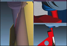
Here is an example of an interference situation. The two right-hand views show that the cutting tool holder has gouged the fixture (these are highlighted in red to alert the programmer to the collision). The workpiece shown on the left side was also gouged. Had this happened on the actual machine tool, the cutting tool, toolholder and fixture would have been damaged, and the machine’s axes likely would have been knocked out of alignment.
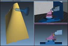
These three windows show different views of a modeled five-axis machine tool. The simulation software can be set up to stop and identify any detected interference between the workpiece, fixture, cutting tool or machine components. This is especially helpful for long-running jobs so programmers don’t have to sit through an entire simulation.
The Advanced Composites Center located on Bell Helicopter’s campus in Fort Worth, Texas, produces composite components for the Bell-Boeing V-22 Osprey vertical lift-off aircraft. The facility manufactures and machines only composite aircraft parts, including blades, spars, wing-skins, yokes and rotor components. After lay-up, these parts represent a significant investment prior to subsequent milling, drilling and trimming operations that are typically required. Scrapping an aerospace part at this late stage of manufacturing because a programming error caused a collision between a machine component and part would prove extremely costly.
Damaging workpieces, however, is only one potential problem that could occur if all possible interferences between machine component, cutting tool, fixture and part aren’t identified before a real machining cycle starts. A few years ago, the center purchased two Cincinnati Magnum 1000 five-axis machine tools to machine critical V-22 parts. At that time, programmers would pass completed machining programs between themselves for verification before dry-running the program on a machine. According to Ronald Tovar, the facility’s supervisor of NC programming, identifying and weeding out every programming issue was difficult even though a team of talented programmers examined the five-axis machining code.


The worst programming error scenario is a collision that results in damage to the machine. That happened twice with the center’s two Magnums. In both cases, the major issue wasn’t that workpieces were scrapped, but that the machines themselves required repair. In addition to the service cost, the center lost 3 weeks of production time while those machines were offline. Mr. Tovar says this is what drove the center to adopt machine simulation software to ensure that only error-free programs were sent to all of the center’s machine tools.
Simulating The Process In 3D
The center adopted Vericut Machine Simulation software from CGTech (Irvine, California) initially just for those two Magnums. CGTech “built” those machines electronically, modeling all the major interacting components just as they would appear on the actual machine. Because the center’s tool design department designed tools in 3D, CGTech was able to import those tool models into machine simulation. The Vericut software could then generate 3D simulations of the entire machining operations directly from a CAM program.
During the simulation, all major components move in relation to each other, just as if one were watching a real machine tool mill a real part. The simulation detects any collisions between components such as machine bed, heads, spindles, cutting tools, toolholders, fixtures and any auxiliary components. It shows the limits of all machine axes which is particularly helpful for complex five-axis movements. It also flags conditions in which feed rates for a given operation are too high, in addition to displaying differences between the desired final part geometry and the Vericut-machined model.
Components that interfere with each other during the simulation will turn red to alert the viewer (the programmer) to a problem (an example is shown to the right). The programmer will then adjust the program to eliminate the interference and re-run the simulation. Machining jobs that have long cycle times also have long simulation replay times, meaning programmers may not be able to watch the simulation start-to-finish. In these cases, the simulation is set up to pause itself when a collision is detected.
Once the simulation verifies that there will be no interferences for a given part program, the center immediately schedules the job without performing trial dry runs. Mr. Tovar notes that there is a 99 percent probability that there won’t be a problem after the program is verified. The center may tweak feed rates and/or spindle speed, but it is assured that parts won’t be scrapped and machines won’t be damaged.
Simulation Spreading To Other Plants
The center doesn’t create each new machine model itself. That’s because the interval between its machine purchases is relatively long. CGTech has modeled other machines in the center in addition to the two Magnums. These include a Trim Cell that combines five-axis milling with waterjet trimming of wing skins; an Henri Liné five-axis gantry that machines rotor blades; and a new Makino four-axis machine. The center recently ordered an SNK five-axis gantry that will also be modeled for simulation.


Related Content

4 Commonly Misapplied CNC Features
Misapplication of these important CNC features will result in wasted time, wasted or duplicated effort and/or wasted material.
Read More
Which Approach to Automation Fits Your CNC Machine Tool?
Choosing the right automation to pair with a CNC machine tool cell means weighing various factors, as this fabrication business has learned well.
Read More
High RPM Spindles: 5 Advantages for 5-axis CNC Machines
Explore five crucial ways equipping 5-axis CNC machines with Air Turbine Spindles® can achieve the speeds necessary to overcome manufacturing challenges.
Read More
Ballbar Testing Benefits Low-Volume Manufacturing
Thanks to ballbar testing with a Renishaw QC20-W, the Autodesk Technology Centers now have more confidence in their machine tools.
Read MoreRead Next

Compliant Machining Of Composite Wings
Bell Helicopter created a systematic, scripted process to machine composite wing skins and structural components for the V-22 Osprey vertical takeoff aircraft. Custom software ensures there is no deviation from the script.
Read More
Building Out a Foundation for Student Machinists
Autodesk and Haas have teamed up to produce an introductory course for students that covers the basics of CAD, CAM and CNC while providing them with a portfolio part.
Read More
Registration Now Open for the Precision Machining Technology Show (PMTS) 2025
The precision machining industry’s premier event returns to Cleveland, OH, April 1-3.
Read More