Moldmaking Made Efficient Using Integrated CAD/CAM
This mold maker benefits from a 3D CAD/CAM package this mold maker uses pays off by speeding the design of new dies and molds, as well as other ways.
Share


My second phone call to Tim Rietsma briefly pulled him away from an atypical job for his die/mold shop: he was gluing a sheet of laminate to the top of an office table.
Though Contour Tool and Engineering moved into its new, 12,000 square-foot building more than a year ago, a large amount of machining work has prevented partners Mike and Tim Rietsma from getting around to making such finishing touches to the facility. That’s a welcome problem for this Zeeland, Michigan, shop to have.
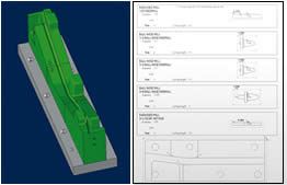
One reason for the shop’s booming business can be attributed to the integrated, knowledge-based 3D CAD/CAM package that has compressed design and manufacturing time for injection molds, stamping dies and tube-bending dies. Mr. Rietsma uses two CAM and two CAD modules from Missler’s TopSolid software platform, which he purchased from Clear-Cut Solutions, located in Addison, Illinois. The integrated platform exchanges native data across all software modules. The benefit of this feature is that it eliminates the need to translate CAD data so that it can be recognized by another vendor’s CAM software. This speeds programming time by eliminating the need to fix geometries. In addition, the 3D visualization of mold and die components and how they interact has been helpful to the shop in demonstrating to customers how a new design will properly function. That makes it an effective sales tool. It also speeds the development of new quotes and allows the company to go after difficult jobs it otherwise might not target.
Faster Programming
Mr. Rietsma first purchased the TopSolid Design CAD module and followed that with TopSolid CAM. TopSolid Mold, the second design module he purchased, offers features specifically tailored for moldmaking. The CAM module recognizes features in the CAD solid model, such as bolts and ejector pins, and automatically generates all the code required to machine features in the mold block for these components.
TopSolid Mold contains libraries of standard mold components, such as mold blocks and pins, from various different suppliers. Not only does this make ordering components easier, but it also eliminates the need to create a component drawing from scratch or modify an existing CAD file for use in the software. In addition, information such as the component’s stock number is contained within the file. If the size of the pin or bolt, as examples, has to be modified, then the software automatically updates related operations in the mold block to accommodate the new component.
The company has found TopSolid Mold to be helpful in designing and machining tube-bending dies. The software is able to identify the split line of a tube that might require bends on multiple axes, then automatically create the surfaces for the two die halves.
Similarly, the capabilities offered by TopSolid Design gave the company the confidence to design a proprietary hydraulic tube bending and punching machine. The machine, which produces an automotive component in one setup, uses approximately 80 blocks to create the bends, flats and holes for the component. It replaced a line of stamping dies that required hand loading and part transfer. The machine maintains a constant grip on the tube throughout the process to maintain accurate feature-to-feature tolerances. Solid modeling allowed Contour to make certain components semi-transparent to visualize how they interact and to ensure there was sufficient clearance between the choreographed moving parts. In addition to the blocks, all machine components, including frame and weldments, were created as solid models in TopSolid. Detailed prints were then sent to a fabricator that manufactured those large components. This machine is the most impressive job the shop has undertaken using the software, according to Mr. Rietsma.
Beyond Speed
The software has not only shortened the time required for Mr. Rietsma to quote a job, but it has also improved quoting accuracy by 70 percent. That’s because the 3D visualization best identifies exactly what he needs to produce before ordering material and machining components. The software can automatically create a bill of material list that can be exported as a text file or an Excel spreadsheet. It also automatically generates a setup sheet, which identifies the necessary cutting tools and their respective tool pocket numbers.
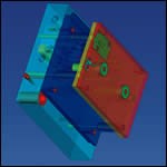
3D visualization proved helpful in allaying a customer’s concern about the protection of a switch’s wire on an inserted mold. Using the solid model, Mr. Rietsma was able to show his customer that a tight radius and pocket for a wire clamp machined in the block would ensure that the wire would not come loose and become pinched between the mold plates.
The software serves as a sales tool, too. Mr. Rietsma sometimes demonstrates to his customers how the software is able to automatically create the machining code for standard mold features to show how that will shorten design time. He also has the option of offering his customers Topsolid’s Viewer software, which is a light CAD program that customers can use to view CAD designs as a whole or by layers, as a mold file may have different layers for injectors, covers and other components.
Read Next
Setting Up the Building Blocks for a Digital Factory
Woodward Inc. spent over a year developing an API to connect machines to its digital factory. Caron Engineering’s MiConnect has cut most of this process while also granting the shop greater access to machine information.
Read MoreRegistration Now Open for the Precision Machining Technology Show (PMTS) 2025
The precision machining industry’s premier event returns to Cleveland, OH, April 1-3.
Read More5 Rules of Thumb for Buying CNC Machine Tools
Use these tips to carefully plan your machine tool purchases and to avoid regretting your decision later.
Read More


.png;maxWidth=300;quality=90)


