Mapping Your Way To Five-Axis Machining
The right route starts with the workpiece, but there are many other considerations.
Share


Hwacheon Machinery America, Inc.
Featured Content
View More
Takumi USA
Featured Content
View More


One thing for certain is the increasing popularity of four-axis and five-axis operations on horizontal machining centers (HMCs).
It's almost as certain this trend will continue—given the magnitude and variety of advantages that multi-axis machining (meaning four- and five-axis here) brings to productivity, product quality, and basic abilities to produce more complex, contoured workpieces.
Not so certain, however, are the answers to questions such as:
- What factors determine whether I should use four-axis or five-axis machining for my particular operations?
- If I should consider multi-axis machining, how many axes might I need?
- For a given level of multi-axis machining capability, what machine configuration can get me there—and which of these choices is the right choice?
The purpose of this article is to help answer such questions and others related to five-axis machining opportunities, considerations, potential pitfalls, and the choices involved when mapping out the most profitable investment in horizontal machining centers.
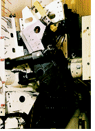
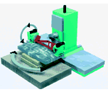
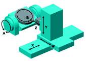
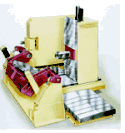
The operative word is "mapping." Just like road maps usually show a choice of routes for driving from point A to point B, so do manufacturing engineers encounter many different considerations when first deciding whether their company's machining centers should include multiple-axis capabilities. And if more than three axes of machining are deemed most appropriate, numerous routes are available to reach four-, five-, and even six-axis capabilities. Figures 1 and 2 illustrate some of the different machine tool configurations that represent various routes to multi-axis capability.
In metalworking manufacturing, of course, the ultimate destination is lowest total cost for processing a given part or family of parts to specified tolerances. Increased productivity is one obvious way that multi-axis machining helps to achieve this goal. But decisions to use five-axis machining also are based upon minimizing the number of machines needed to completely process parts, as well as on needs for more uniform machining accuracy and improved product quality.
Whatever benefits of multi-axis machining have highest value, the decisions on "whether" and "how much" involve a variety of considerations.
It All Starts With The Workpiece
Not surprisingly, the first set of considerations begins with the workpiece itself—size, geometry, weight, type of material, as well as number, type, and variety of features to be machined on each part.
Additional considerations related to the workpiece alone include variations in part configuration; number of different part sizes to be processed; particular features to be machined; locations of each machined feature on the workpiece; size of workpiece opening that a tool must pass through to reach the machining location; and the specified machining tolerances.
The objective in all cases is to provide optimum tool positioning. More specifically, to provide the fastest cutting tool access to individual workpiece locations, with the tool and part surface oriented at correct angles to each other for uniformly accurate machining of required features with the highest overall performance (that is, metal removal rate). Inherent to achieving this objective is moving the least amount of mass—whether it is the workpiece or the multi-axis machine elements.
Highest overall performance includes a separate set of considerations related to both the workpiece and its entire production process.
Only an understanding of the individual manufacturing operation can develop the full intelligence needed to evaluate whether and how much that process can benefit from five-axis machining. Examples here include realistic suggestions for reducing the total number of machines needed to completely process a given group of parts, for eliminating specific numbers of separate workpiece setups, for minimizing work-in-process inventory, and for estimating anticipated gains in door-to-door total manufacturing time. Likewise, floor-level manufacturing know-how is needed to understand the possible limitations as well as the attractive advantages of a given five-axis machining system.
Potential future products also can influence decisions on whether, how much and what configuration of multi-axis machining should be employed. In addition to present workpieces, what new parts now being designed are scheduled for production within the next few years? How many of the planned future parts are candidates for five-axis machining?
Production volumes required for any workpieces are still another consideration for multi-axis machining decisions. Typically, however, volume is not as important as other factors.
Though the number and variety of considerations involved with five-axis evaluations may sound like the decision-making process is complicated, in reality "the right route" often makes itself apparent quite early. This happens more often when "the big picture" is kept in mind while specific issues and choices are being addressed.
Keep "The Big Picture" In Mind
Considerations for five-axis machining should not be restricted to a machine alone. It is important to recognize, understand and continuously view multi-axis decision-making as a true optimization process.
Certainly the horizontal machining center and its various configurations to cut chips along more than three axes provide the basic structure for positioning a cutting tool to specific workpiece locations, and then allowing that tool to remove metal most productively and accurately.
Along with considerations for machine axes' combinations, however, equal thought must be given to spindle horsepower and rpm, cutting tools, fixturing, controls, programming, and possible attachments, as well as requirements for material handling. Each of these elements has a role in determining whether and which physical form of five-axis machining is most appropriate for a particular situation. Collectively, they comprise a "stack" of technologies integrated as a system in order to remove metal as quickly and accurately as possible.
Five-Axis Machining: Who Needs It?
Some workpieces require five-axis machining capability in order to be produced at all. These include more complex contoured parts such as mold cavities, blisks (bladed-disk parts), impellers, and other turbine-type parts where tool orientation must be controlled in order to reach a surface to be machined. Also in this category are workpieces that have machined-feature locations facing interference from other features on the same part, and workpieces with surfaces that simply can't be reached by rotating about just one axis.
Even where parts can be produced on three-axis machines, economic considerations like the following often reveal that five-axis machining offers lowest total cost door-to-door:
- Potential costs saved by reducing the volumes of machines, tooling, and fixturing presently required to achieve the same end result;
Value of increased throughput—including time saved by eliminating separate setups and reducing queue times required for separate-machine operations; - Value of current in-process inventory that will not be needed with multi-axis machining capability;
- Value of reduced scrap and rework made possible by complete machining in a single setup, reduced part handling, more uniform machining accuracy;
- Value of time and costs saved in quality control and inspection.
All of these potential cost savings and others, of course, must be weighed against the higher initial investment required for five-axis machining capabilities.
When the economics justify investment in five-axis machining, a whole next set of choices drives the process of deciding which physical forms will add the desired axes capabilities most cost-effectively. The same considerations help decide which technology source you choose to work with.
Which Route Should You Take?
Because mapping the right route to five-axis machining is a true process of optimization, the possible choices involve various degrees of "give-and-take." Thus, there often is not one literally "right" answer, to the exclusion of all other choices. Instead—just as with the road map when traveling by automobile—the forces of personal preference and individual comfort frequently are involved.
In general, though, the "sign posts" that follow provide some guidance to help pick out the right road and to avoid major detours.
For reference, Figure 3 represents a six-axis machining center (being used in the aerospace industry). The machine's Z axis is a ram that houses the spindle and can travel into the heart of a workpiece. This is in addition to the standard W-axis cross-slide motion. Together, the Z and W axes provide up to 60 inches of collinear travel. For the rotary tilt table in this illustration, the B axis designates rotary motion; the A axis designates table tilt motion.
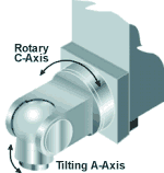
Figure 4 represents another route for building multiple machine axes—the two-axis tilt/rotary (swiveling) spindle. In this particular design, the tilting A-axis travel is ±120 degrees. Rotating C-axis travel is ±180 degrees.
Beyond the X-, Y-, and Z-axis motions of an HMC, the most common methods for achieving four- and five-axis machining capabilities include:
- Tilt table—A axis added;
- Tilt and rotary table—A and B axes added;
- Twin tables-on-a-table—A and B axes added;
- Table-on-table—B and C axes added;
- Tilt spindle and rotary table—A and B axes added;
- Tilt and rotating (swiveling) spindle—A and C axes added.
A- and C-axis motions can be added either with an integral A/C-axis head built into the machining center, or in attachment form. Figure 5 shows an example of this configuration.
The integral A/C-axis head would be considered when a part is so large that it is difficult to move for the orientation of the A and C axes. Adding A- and C-axis motion through the headstock (on the tool side versus the workpiece side) can sometimes allow a smaller, simpler machine to be used.
The integral A/C-axis head arrangement also works well for five-axis machining of pockets in long aerospace components and in machining the ends of such parts. Attachments are commonly used for machining along the A and C axes on larger machines where the attachment forms add versatility to process larger parts.
In some cases, the optimum arrangement is to rough-machine along the X, Y, and Z axes, taking heavy cuts at higher speeds and feeds. Then an attachment performs lighter finishing operations on the A and C axes. In other cases, where the A and C axes also require rough machining operations, the integral head arrangement takes advantage of base machine horsepower and rigidity.
Since moving the least amount of mass is fundamental to achieving highest overall performance, it follows that early consideration will be given to a tilt/rotary spindle where heavy workpieces are involved. The spindle to be tilted and/or rotated may have less mass than the workpiece to be tilted and rotated on a table for presentation to the cutting tool.
Workpiece weight also must be compared against a table's tilt capacity and other factors, such as cost. Where workpieces are heavy, but still within a table's tilting capacity, the choice between tilt table and tilt spindle might depend upon other factors, such as size of the part envelope.
In the experience of Giddings & Lewis, a tilt/rotary spindle generally is used for five-axis machining of parts larger than 60 inches (1520 mm) cube size. Lengths and heights of these parts may measure many feet or meters.
For many small to mid-size prismatic parts, five-axis machining is achieved using a tilt/rotary table, where the rotary axis (B) sits on top of the tilt axis (A). Typically, the space envelope of a tilt motion needs substantial Y-axis travel. Tilting the workpiece (instead of the spindle) helps to simplify the spindle head design.
A variation of adding A- and B-axis machining capabilities is a configuration where twin A-axis contouring tables are mounted on a B-axis table that rotates ±30 degrees. See the box on page 106. Both A-axis tables have 360,000 positions, and hold long, heavy workpieces between centers with full contouring capability.
A second table-on-table configuration adds B- and C-axis motions. In the version shown in Figure 6, one C-axis table that can rotate 360 degrees is mounted on top of a B-axis table that can rotate 320 degrees.
Where pallet shuttle systems are involved, with parts set up off-machine, tilt/rotary tables or tilt/rotary spindles are the five-axis machining methods of choice over table-on-table configurations.
The single table-on-table version is used for five-axis machining of small blisk parts and longer workpieces with small diameters when spindle design needs to be kept simple. Long rectangular or cylindrical parts not well-suited to tilt tables may be better suited to twin A tables over B because of their length.
Parts such as airfoils and turbine blades are best machined using a tilt spindle and rotary table or the table-on-table configuration. Either method allows shorter tool reach into the workpiece. Sometimes, the choice between these two methods may be determined by associated fixturing or the manufacturer's personal preference.
Pon-rotating tilt spindles and rotating tables normally are teamed to process large ring-type parts such as jet engine casings. The reason is that typical workpieces in this class have many holes, and the spindle is working all around the circumference of a part. In most applications, it is easier to rotate the ring-type part and tilt the spindle than it is to both rotate and tilt the spindle or to rotate and tilt the part.
The basic need to orient workpiece and cutting tool at correct angles to each other also presents choices. Consider the case where holes are to be drilled and tapped at an angle. If only two or three angle holes are required, a tilt spindle may be the best answer. On the other hand, if a large number of angle holes are needed, keeping the spindle fixed and using two-axis departure with a tilt/rotary table are more likely to maintain hole accuracy and uniformity.
When addressing workpiece size, required axis travel also may need to be considered in order to arrive at the best five-axis machining method. Linear range of travel needed is fairly easy to identify. Rotary range of travel is more difficult because it depends on the process selected to orient the cutting tool to the workpiece.
More Than Machine Axis Motions
As emphasized earlier, decisions on five-axis machining involve far more than axes motions of the machine per se.
Part of the aforementioned "big picture" to keep in mind at this point is to recognize that—in order to create four, five, and even six axes of machining center motion—it is necessary to "stack" each additional axis on top of another. The task is to determine which "route" or stacking of axes will provide optimum strength and stiffness to remove metal fastest and most accurately.
Whatever machine configurations are decided upon to add axis motions, each "stacking" adds a point of connection or fastening. Each connection can increase the chance of positioning errors. The further out in the stack, the weaker each element of added axis becomes. Highest overall five-axis machining performance requires minimizing the weakest connection in the stack. Therefore, a basic objective is to establish the primary axes in their most solid forms first; then build on these primary axes with the stiffest possible combinations.
Among the first considerations in this stacking sequence are the spindle capabilities required for individual machining operations. For example, do most of those operations require high horsepower at low speed, or medium horsepower at high speed?
As spindle speeds increase, cutting forces decrease. But just because spindle rpm doubles doesn't mean metal can be removed in half the time. Different types of machining operations and parameters impose different dynamic forces on the machine. The machine and spindle together need the capability to contour fast and accurately at high rates on the programmed part path. As machines get larger, achieving dynamic accuracy becomes more difficult.
The majority of five-axis machining operations require less spindle power than three-axis applications do because the typical tooling used on fourth and fifth axes can't support heavy cuts. In addition, many workpieces machined on five axes have thin-walled sections that can't withstand higher cutting forces.
The above also suggests how closely related the considerations for tooling are to those for spindle requirements. Certain workpieces may require small-diameter tools to machine small radii, but also long tools for reach. The cutting tools then become the limiting factors that determine depth of cut and feed rate for operations such as pocket corners on aircraft wing structural components and hub areas of turbine blades.
Tooling is recognized as a common weak point in the component stack-up for multi-axis machining. Nevertheless, a frequent error remaining in five-axis machining decisions today is the attempt to tool up a high performance machine with cutting tools that are inappropriate to match machine metal-removal rates.
Helping to make today's tool connections stiffer and stronger are shrink-fit tools and hollow shank (HSK) tools.
A different tooling consideration involves carbide versus high speed steel cutters. HSS cutters cost less initially, but can be responsible for a much costlier limitation in overall machining performance. The same cutter geometry in carbide form will be stiffer. Sometimes a carbide cutter can provide all the increase in stiffness needed for the tool length being used.
Fixturing also can be a major influence on overall system stiffness, but trade-offs come into play here too. An example is the desire to keep fixturing mass as low as possible in the work zone while simultaneously providing sufficient rigidity for the cutting process. Fixturing is further complicated by issues of interference with machine movements and limits for tool access.
Other fixturing trade-offs include the desire to support parts at points of heaviest cutting forces wherever possible. While this enhances workholding rigidity, the related additional fixture weight can limit overall machine performance in other ways. Likewise, clamping more part locations can improve stiffness, but the added fixturing clamp points also may require more space in the work zone. This also can create clearance problems.
CNC Considerations For Five-Axis Machining
One of the most important CNC (computer numerical control) considerations for five-axis machining is block processing time.
Typical five-axis curved surfaces are generated by commanding a series of short linear moves that make up the overall contour path. In addition, today's advanced machining centers also move faster. Together, these require processing a large number of blocks in a short period of time.
To avoid block starvation on multi-axis machining, therefore, block processing time for the CNC must be less than the minimum block length in inches divided by the maximum feed rate programmed, in inches per second.
Using the values shown in parentheses as an example, a specific number for block processing time can be determined by:
a) Computing the minimum block length to be programmed (0.010 inch);
b) Dividing (a) by maximum feed rate programmed, in inches per second (120 ipm = 2 inches per second).
For this example, CNC time to execute the shortest block length programmed should be less than 0.005 second (0.010 inch ÷ 2 = 0.005 second).
Part program storage capacity is another important control consideration. Most five-axis programs are larger than three-axis programs. The fastest way to execute five-axis programs is typically from part-program memory. Therefore, the machining center CNC should have memory capacity larger than the largest program to be executed.
Other methods of program execution are DNC (direct numerical control) communication to run programs from a host computer. Or, execution of programs from CNC disk drives, if they exist.
Programming Considerations
As with controls, user-friendliness is one of the major considerations for generating five-axis part programs. Whereas the CNC must be friendly to the operator, computer-aided manufacturing (CAM) tools should be as compatible as possible with whatever computer-aided design (CAD) system or other design tools the manufacturer has. No one wants to re-create a CAD design for manufacturing purposes.
A similar software consideration is making sure that a CAM system can convert its output to part-program commands that the machine's CNC can use. This output also must consider the machine limits, so that a machine is not commanded beyond its travel or feed rate constraints.
The value of program simulation increases with the complexity of five-axis machining. Therefore, a key consideration is whether the simulation software can handle whatever configuration of five-axis machining center is being planned. In order to identify and avoid potential collision points, software must be able to appropriately simulate the specific workpieces to be processed, as well as the planned machine configuration, cutting tools, fixturing, and other five-axis machining elements.
Avoiding The Rough Roads
In mapping out your best route to five-axis machining, it's only prudent to check the "road reports" from those who have traveled before you. Some of the more common words of advice to help avoid costly detours include the following:
- Invest in high quality machines. Resist temptations to buy "the lowest priced car on the lot." There are too many ways this can cost you much more money later on. The continuous operation and higher performance expectations of five-axis machining demand deep machine strength, longer durability, and sound design innovations.
- Work with machine tool builders who truly understand manufacturing processes in addition to their machines. Some of the reasons why process know-how is so important to maximize the return on investment in five-axis machining have been identified in this article. But if the values of process experience still seem remote or somewhat intangible as you investigate five-axis machining, talk to the people who already use such technology.
- Explore the alternatives. A wealth of technology for five-axis machining exists already. More is being developed and implemented every day. The considerations introduced here are only the tip of the iceberg. The people earning fastest paybacks on their five-axis machining investments are those who take the time and effort to identify the many choices available; who use their intuition and gut feelings when exploring those choices; and who keep "the big picture" foremost in mind while deciding which choices best fit their individual product, process, and machining needs.
Finally, if all other factors seem equal (and they rarely do), select the route to five-axis machining that looks simplest and easiest to maintain.
About the author: Kenneth J. Campshure is a product manager at Giddings & Lewis Automation Technology, Fond du Lac, Wisconsin.
Related Content
Ballbar Testing Benefits Low-Volume Manufacturing
Thanks to ballbar testing with a Renishaw QC20-W, the Autodesk Technology Centers now have more confidence in their machine tools.
Read MoreCNC Machine Shop Honored for Automation, Machine Monitoring
From cobots to machine monitoring, this Top Shop honoree shows that machining technology is about more than the machine tool.
Read MoreOrthopedic Event Discusses Manufacturing Strategies
At the seminar, representatives from multiple companies discussed strategies for making orthopedic devices accurately and efficiently.
Read MoreQuick-Change Tool Heads Reduce Setup on Swiss-Type Turning Centers
This new quick-change tooling system enables shops to get more production from their Swiss turning centers through reduced tool setup time and matches the performance of a solid tool.
Read MoreRead Next
Registration Now Open for the Precision Machining Technology Show (PMTS) 2025
The precision machining industry’s premier event returns to Cleveland, OH, April 1-3.
Read More5 Rules of Thumb for Buying CNC Machine Tools
Use these tips to carefully plan your machine tool purchases and to avoid regretting your decision later.
Read MoreBuilding Out a Foundation for Student Machinists
Autodesk and Haas have teamed up to produce an introductory course for students that covers the basics of CAD, CAM and CNC while providing them with a portfolio part.
Read More





.jpg;maxWidth=300;quality=90)
.jpg;maxWidth=300;quality=90)


