Making Machines Move Faster
A convergence of motion control and mechanical technologies is allowing machine tools to achieve remarkable levels of accuracy at breathtaking speeds.
Share


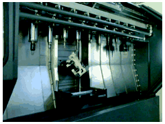
While a high speed machining center may look a lot like its conventional counterpart from the outside, it is in fact technology of a very different order. It's not just a matter of using high speed spindles. Underneath the sheet metal is a cadre of enabling technologies that have moved way beyond what was considered state-of-the-art only a few years ago. Virtually every aspect of the servo control system has been upgraded and, if the design is truly optimized, the fundamental mechanical design strategy has been altered as well.
As with the high speed machining process itself, much of what we think we know about sound machine construction may no longer be valid when it comes to making machining centers capable of moving accurately at speeds measured in thousands of inches a minute. From the control architecture right on down to the bearings, machine tool builders are rethinking how the CNC machining system is supposed to work. And they are drawing upon developments in a host of supporting technologies to reach levels of performance that are simply astonishing by any conventional measure.
Component by component, here's a look at the enabling technologies of a high speed machining center. Note, though, that building a good machine takes more than applying state-of-the-art components—as if that were itself an easy thing to do. The builder must achieve a harmony of all these elements to construct a machine capable of truly extraordinary performance.
Spindles
Bill Popoli of Ibag North America (Milford, Connecticut) leaves little question as to what is foremost in the minds of those who design spindles: "As spindle builders, we live in a world of bearings. This is the most important component." And so it is with high speed machining, only more so.
Lower speed spindles often use steel ball bearings lubricated with grease. But as the speeds go higher that design is no longer adequate. "At some point grease is going to create heat which begins to impact accuracy and life—somewhere around 10,000 rpm, depending upon spindle size," says Tom Klahorst of spindle manufacturer Setco Co. (Cincinnati, Ohio). "Then at about 12,000 rpm you run into other problems, mostly having to do with amplifying residual forces that may be in the whole spindle assemly and its tooling." And speed isn't the only issue. Increasingly, users are demanding both high horsepower and high rpm—a challenge to which the leading spindle makers are responding.
Current technology utilizes hybrid ceramic bearings in combination with oil lubrication, which is appropriate for spindles in the 15,000-rpm range and above, says Mr. Klahorst. Setco has employed this technology for speed-and-power combinations as high as 20,000 rpm/75 hp and 30,000 rpm/50 hp. The bearings still have steel inner and outer races, but the rolling elements are made of a very rigid and durable ceramic material. The ceramic manufacturing process is such that the balls are rounder than steel, and they are less inclined to deform in operation. Because the material is also lighter and more thermally stable than steel, the hybrid design runs much truer and cooler.
As for the lubrication, heat is the enemy of precision and longevity in any bearing, and measures must be taken to manage the problem at high spindle speeds. Spindles operating above 10,000 rpm will typically use an air-and-oil metering system. These systems provide minimal (but sufficient) lubrication to the bearings to generate less heat, and the air flow provides the added benefit of carrying heat away. Additional heat transfer can be achieved via a recirculating coolant system, sometimes referred to as a "chiller."
Bearing design will continue to evolve as speeds and power grow progressively higher. Already the "40/40" spindle—which delivers both 40,000 rpm and 40 kW of power (about 53 hp)—is finding favor in the aerospace industry. Fischer Precision Spindles (Middlefield, Connecticut) makes such a design and, according to the company's Peter Kiro, they are currently in development of a "50/50" design.
Taking the combination of speed and power to higher levels will be challenging, more from a cost and manufacturing standpoint than design. Everything has to be round and balanced to the extreme, and the harmonics of the entire system must be painstakingly worked out in order to keep the onslaught of excessive vibration as far at bay as possible. Indeed, it takes Fischer almost three months just to manufacture the shaft for the 40/40 spindle, after all the machining, hardening, grinding, and balancing is done.
Alternative low friction designs are finding favor in some circles. For instance, the 50-hp, 20,000-rpm spindle used on the High Velocity Modules from Ingersoll Milling Machine Co. (Rockford, Illinois) use a combination hydrostatic/hydrodynamic bearing that has the spindle turning on a journal of fluid rather than hard rolling elements. Air bearings are sometimes used in very high speed applications, generally for relatively small spindles turning in excess of 100,000 rpm. Virtually frictionless magnetic bearings have been used in some cases as well. According to Mr. Popoli, Ibag has successfully applied magnetic bearings in a number of special high speed milling applications. Moreover, this technology offers great development promise due to the ability to adaptively control spindle characteristics through real-time modulation of the magnetic field.
But rolling element bearings continue to be the staple of today's high speed spindle technology, and may well have a large role for some time to come. "Hybrid ceramic ball bearings got us into this generation," says Mr. Kiro. "The next generation will be pure ceramic, including the races." That technology exists today, but at $30,000 to $40,000 per set of all-ceramic spindle bearings, there is a cost barrier yet to be overcome.
Controls
As a practical matter, however, spindle technology has historically proven to be less of a limitation on the high speed machining process than motion control technology, or at least for those who wanted both high feed rates and accuracy. But CNC builders have moved light years in the recent past, thanks largely to the availability of powerful computer processors, sophisticated software and other digital technology.
First of all, CNCs today simply can process a part program much faster. Several CNC makers now boast of block processing times of less than a millisecond on their high performance controls—very speedy performance indeed compared to the 70 milliseconds that would have been considered fast a decade ago. Users need to be wary, though, of exactly what a vendor may mean by block processing time. "It's not just the time it takes to process the program data that is important," says Scott Rohlfs of Mitsubishi Electric Automation (Vernon Hills, Illinois). "It's the time it takes to process, initiate, and finish the move that really matters."
That's a critical point to understand, he says, because the true execution time will define how fast and/or how precisely you can machine. In this context, precision means the tolerance used to generate a conventional point-to-point contouring path executed with linear interpolation. The more accurate the program (relative to the base reference geometry), the more points are required to describe the tool path, and the shorter the distance between points. Dense point spacing can result in a phenomenon that experienced die and mold machinists know all too well as "data starvation," when the CNC can no longer process a program fast enough to keep up with the feed rate. However, at Mitsubishi's high-end processing-and-execution rate of 0.89 milliseconds, a well tuned machine tool can still maintain a feed rate of 675 ipm with points spaced just 0.010 inch apart.
Equally important to accuracy is how well a machine tool can stay on its programmed path, and today's high end CNCs apply sophisticated algorithms to achieve a remarkable combination of precision and speed. How remarkable? GE Fanuc (Charlottesville, Virginia) contends that with the latest all-digital CNC hardware it is now possible "to achieve contouring rates of up to 1,500 to 3,000 ipm while maintaining accuracy as high as 3 to 5 microns," though this level of performance also requires state-of-the-art servo technology, which we'll get to in a moment.
A little closer to home, most shops will be happy to stay within a few "tenths" at a programmed feed rate of 500 ipm, and today's better CNC technology has software features that render it quite capable of doing all that and more. For instance, virtually all higher level controls these days have "look-ahead" capabilities that scan ahead in a part program looking for abrupt changes in direction in the commanded tool path. Then when the CNC "sees" the turns coming, acceleration/deceleration routines are automatically triggered so as not to overshoot the intended path or to undercut external corners due to servo following error.
Some control and machine tool builders enhance this capability with software to further optimize performance. For instance, Makino (Mason, Ohio) augments its Fanuc 16 M C controls with its own 64-bit "Super Geometric Intelligence" card encoded with software that works in conjunction with the CNC's 120-block look-ahead capability. It allows the NC programmer to use the maximum desirable feed rate, and the control system dynamically adjusts feed rates and acc/dec—slowing down for the tight curves and then quickly speeding up for the straighter moves—based on the inertial characteristics of each individual machine and the required level of accuracy for the job.
Executing such capabilities also requires an extremely responsive servo system, tightly integrated with the tool path processor. As such, for all the talk of open architecture in CNCs, don't look for it happening in these finely-tuned control loops anytime soon. The leading builders are tending toward complex distributed control architectures. Besides multiple high speed processors in the CNC that share various real-time control tasks, some systems also utilize "smart" digital axis drives. For the sake of speed, feedback loops go directly back to the drives, rather than to the CNC, though the control does monitor overall system accuracy.
A completely digital system provides opportunities for further control enhancements. For instance, by G-code command, the Mitsubishi 500 CNC can be switched into "high precision control mode" to increase accuracy and reduce cycle time. Normally, acceleration and deceleration are factored at a constant rate, but in this mode they are calculated as a function of the feed rate. Moreover, control algorithms can soften the beginning and end of acc/dec moves into a gentler "S curve," which will result in significantly smoother servo system performance. Adaptive digital filtering can even be used to suppress system vibrations within a certain frequency range.
Particularly interesting is a momentous paradigm shift now underway in how contouring programs are executed. Since the beginning of NC, it was necessary to approximate most curved tool paths as a series of straight-line moves. But with the advent of NURBS interpolation, it is possible to import curves of virtually any complexity into the CNC and machine directly from them (see sidebar). Besides providing a smoother and more accurate surface, NURBS interpolation appears capable of rendering block processing limitations irrelevant and allowing programs to be executed substantially faster than with comparable point-to-point contouring techniques.
Putting It All Together
Fast spindles and controls notwith-standing, building a capable high speed machining center requires much more than a grasp of component technology. "The important thing for people to understand is that a high speed machining center is an integrated system," says Steve Colsten of Makino's Die/Mold Division. And that has equipment manufacturers rethinking just about every aspect of how to build machine tools.
Central to the mechanical system requirements is the ability to accurately move the machine's linear axes at much higher rates of acceleration and speed—and then to manage all the trouble that creates. The major culprits here are heat and vibration.
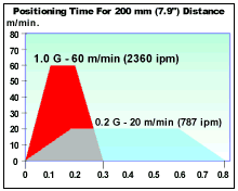
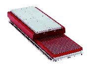
As for axis speed, simply putting faster, higher torque servomotors on existing ballscrew structures isn't going to get the job done, at least in the higher performance ranges. And it is here that some of the most interesting development work is being done in all of motion control. The leading edge of technology currently is the use of linear motors to power axis movement rather than the conventional approach of using ballscrews powered by rotary motors (see sidebar). Linear motors are incredibly quick, stiff and accurate when combined with high resolution linear feedback scales. And it is to machines so equipped that GE Fanuc refers when they speak of 3-micron accuracy and 3,000 ipm in the same breath. Moreover, current linear motor machines can achieve acceleration as high as 1.5 G (which is particularly important to permit both high precision cutting at high feed rates and to reduce non-cutting time in production applications). These are extraordinary numbers compared to what the control builder characterizes as "traditional high speed machines" that cut in the range of 300 to 500 ipm with 25-micron accuracy and acceleration of 0.5 G.
To date, only a handful of machine tool builders have introduced linear motor machines—including Ingersoll, Ex-Cell-O, Kingsbury, and Hitachi Seiki—all of which are aimed at production machining. But more are sure to come. With the likes of Fanuc and Mitsubishi now in the business of providing "pre-integrated" linear motors and control systems, the technology appears likely to become more broadly applied very soon.
But linear motors aren't the only way to get fast axis drives. For instance, Mazak (Florence, Kentucky) is achieving acceleration rates of 1 G and rapid traverse rates of 2362 ipm with the ballscrews on its FF-510 horizontal and FJV-20 vertical machining centers. According to Mazak's Chuck Birkle, the FF-510 is designed to cost effectively produce medium to large lots of automotive parts at close to transfer line levels of productivity where drilling and tapping account for the bulk of the machining. The design employs a longer pitch ballscrew with a double lead to get more linear motion per revolution of the servomotor, yet still can achieve accuracy of ±0.0002 inch with a high resolution feedback encoder, says the builder.
This and other high speed ballscrew designs require special thermal considerations lest the buildup of heat from larger-than-normal servos and friction begin to degrade system accuracy. As such, builders are increasingly doing things like running circulating oil through the ballscrew and around the servos to help maintain a thermally stable platform. Some builders place thermal sensors in several strategic locations all around the machine, and the data they collect is used to control a chiller drawing heat from the frame and spindle of the machine.
The other critical aspect of machine tool design, and perhaps the most daunting challenge for their builders, is how to make a machine with both low inertia in its moving members and the structural stiffness to resist falling prey to the increased propensity for vibration that comes along with high speed machining. At once it would seem that castings need to be lighter to move faster and heavier to absorb the shocks. Or at least that's how conventional thinking would have it. But unconventional is the watchword now, and builders are growing increasingly bold in their designs. Box ways are quickly giving way to linear guides that use ball or roller bearing trucks to reduce friction and inertia, for instance, even on high powered machines. And through computer-aided engineering techniques, builders are indeed finding ways to add rigidity to castings while reducing weight.
But that's only the beginning. Like this process in general, we are probably now just getting a glimpse of what a high speed machine will eventually become.
Related Content
How to Accelerate Robotic Deburring & Automated Material Removal
Pairing automation with air-driven motors that push cutting tool speeds up to 65,000 RPM with no duty cycle can dramatically improve throughput and improve finishing.
Read MoreRead Next
5 Rules of Thumb for Buying CNC Machine Tools
Use these tips to carefully plan your machine tool purchases and to avoid regretting your decision later.
Read MoreRegistration Now Open for the Precision Machining Technology Show (PMTS) 2025
The precision machining industry’s premier event returns to Cleveland, OH, April 1-3.
Read MoreSetting Up the Building Blocks for a Digital Factory
Woodward Inc. spent over a year developing an API to connect machines to its digital factory. Caron Engineering’s MiConnect has cut most of this process while also granting the shop greater access to machine information.
Read More


.gif;width=860)
.gif;width=860)
.gif;width=860)
