Key CNC Concept #8—The Modes Of Machine Operation
This concept introduces the three basic modes of operation, presents examples of when they are used, explores more about the mode switch, and categorizes each position of the mode switch into one of the three basic modes.
Share


This is the eighth article in a 10 part series about the key concepts of CNC. To start at the beginning, read this article.
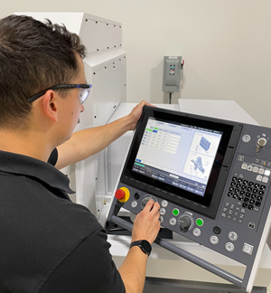
During key concept number seven, we discussed the mode switch found on the machine panel. We said this switch was the heart of the CNC machine and that the operator must first look at this switch before any function can be performed. The most common mistake on the operator's part is having the mode switch in the wrong position.
Also during key concept number seven, you found that the mode switch has several positions. However, during this key concept, you will find that there are really only three basic modes of operation.
Here we will introduce the three modes and give examples of when they are used. We will also discuss more about the mode switch, categorizing each position of the mode switch into one of the three basic modes.
Manual Mode
In the manual mode, the CNC machine behaves like a standard or conventional machine. A CNC machining center behaves like a manual milling machine. A CNC turning center behaves like an engine lathe. The physical positions of the mode switch that are included as manual modes include manual or jog, handwheel, and reference return.
With the manual mode, the operator of a CNC machine is allowed to press buttons, turn handwheels, and activate switches in order to attain the desired machine function. The activation of each button or switch in the manual mode has an immediate response. For example, if the correct mode switch position is selected and if the correct button is pressed, the spindle will start. If a switch is turned on, the coolant will come on. If a joystick is held in one direction or another, the corresponding machine axis will move.
Note that those things that cannot be done in the manual mode must be done in the manual data input mode, the second mode of operation.
Manual Data Input Mode
This mode includes two positions on the mode switch, the edit position, and the manual data input (MDI) position. In each case, the operator will be entering data through the keyboard on the control panel and display screen.
Though these mode switch positions have substantial differences, we consider them together for two reasons. First, both mode switch positions involve entering data through the keyboard. With the edit position of the mode switch, a program is entered or modified. With the MDI position of the mode switch CNC commands are entered and executed.
Second, both provide manual capabilities that can also be done in a more automatic way. In edit mode, an operator can enter CNC programs into the control memory. This can also be accomplished by loading the program from some outside device, such as a computer or tape reader. In MDI mode, CNC commands are entered through the keyboard and display screen manually and can be executed once. If the command must be executed a second time, the operator must enter the MDI command a second time. However, if the same command is included in a program, it can be executed automatically, over and over without having to be re-typed.
Manual Data Input
Almost anything that can be done within a CNC program can be done in the MDI mode. If an operator is proficient with CNC commands, many times they can perform functions more quickly with MDI than they can by other manual means. For example, the reference return position can be attained through manual means (the reference return mode of the mode switch) and through MDI commands. A good operator can perform this operation faster in the manual data input mode.
But the most important reason for the MDI mode is to allow the operator to perform manual operations that are not possible by using the manual mode. For example, some machining centers have no manual buttons or switches to select the spindle speed, direction, and turn the spindle on and off. With this type of machine, if the operator needs to manually turn the spindle on for any reason, they must use MDI to do so. In the same way, some turning centers have no manual means with which to change tools and thus must use MDI commands.
The manual data input mode switch position can even be used for machining a workpiece. Since almost all CNC commands are possible by MDI (including G00, G01, G02, and G03), the operator can make machining commands in a way similar to how they are commanded in a CNC program. However, the operator must be very careful when using MDI to machine work-pieces. The command will be executed as entered. If the operator makes a mistake in the MDI mode, disaster could result. There is no chance to verify a CNC command executed by MDI as can be done with a CNC program.
Edit Mode
If you have ever worked with a word processor, you will find the use of the edit mode of a CNC control familiar and easy to work with. In this mode, the operator is allowed to do two basic things. He can enter CNC programs into the control memory and modify current programs. Almost all CNC controls allow the operator to store multiple programs. Programs are typically organized by program number (commonly the O word). The operator will be allowed to call up the desired program from within the control's memory, making it the active program.
All true CNC controls give the user the ability to do at least three basic things in the edit mode. The operator can insert new information into the program, alter the current information in the program, and delete information from the program. Some CNC controls also allow the operator to do global editing, meaning they can cut and paste, and find and replace data.
Along with these basic features, the operator will be allowed to search or scan the program for key information. For example, the control can quickly search to the next occurrence of any programming word. If the programmer used sequence numbers (N words) the operator could use the sequence number of an incorrect command as the word used to search.
Program Operation Mode
The third mode of operation involves actually running programs. The two positions of the mode switch are memory (or auto) and tape. The operator uses this mode to verify programs and run production.
The memory (or auto) mode is used to execute programs from the control's memory. As long as the control's memory is of sufficient size to hold the entire CNC program (as it almost always will be), the memory mode should be used to execute the program.
While there could be several programs stored in the control's memory, only one is active. This is the program that will be run when the cycle start button is pressed. On most controls, the edit mode is used to choose the active program.
With most CNC controls, while a program is being executed from memory, the programmer is allowed to see one full page of the program on the control's display screen. As the program is executed, the cursor will scroll through the program, letting the programmer see the commands that follow the command currently being executed.
Tape Mode
At one time, the tape mode was the only way to activate programs. But with the advent of the computer, the need for the tape mode switch has decreased. In fact, many CNC controls do not even come with the ability to run programs from the tape reader. While they may equip the control with a tape reader, its sole purpose is to load programs into the control's memory.
For those CNC controls that still allow programs to be executed from the tape mode, there are only two occasions when this is helpful. Both involve programs that are too long to fit into the control's memory. First, a program can be run directly from the tape reader (if the control allows this function). However, the tape reader also has a limitation in the length of program it can run.
For those extremely long programs, some CNC controls allow programs to be run from an outside device like a personal computer. With this technique, the control is fooled into thinking it is running a program from the tape reader, but in reality it is running a program being transmitted through the control's communications port. To accomplish this, the mode switch position is set to the tape mode while the program is executed. But the control's parameters are set in a way that tell the control to run from the communications port. The main application for this technique is for three dimensional sculpturing CNC programs generated from a CAM system. With these programs, very tiny motions are generated to machine elaborate contoured shapes. Direct numerical control (DNC) is the term used to describe this technique of running programs from an external computer. Keep in mind that this is an extremely necessary feature for certain applications, like machining dies and molds.
The tape position of the mode switch has two severe limitations. First, the operator will only be allowed to see one or two commands of the program at a time on the display screen. In memory mode, the operator will be allowed to monitor a whole page of the program. This is most helpful during the program's verification, when the operator wishes to check the commands coming up.
The second limitation of the tape mode is that modification of the program is not possible from within the CNC control. This means the program must be perfect before it can be run. If changes must be made, they must be made away from the CNC control. When programs are stored in the control's memory, it is easy to make changes right at the control.
This is the eighth article in a 10 part series about the key concepts of CNC. To start at the beginning, read this article.
Next Article - Key Concept Number 9 - The Key Sequences Of Operation.
Related Content
Swiss-Type Control Uses CNC Data to Improve Efficiency
Advanced controls for Swiss-type CNC lathes uses machine data to prevent tool collisions, saving setup time and scrap costs.
Read MoreFrom Tradition to Transformation: Century-Old Manual Machine Shop Adds CNCs
After 122 years of working with manual mills and lathes, this fifth-generation shop acquired assets of a local CNC machining business and hired the owner. Here’s how it’s going a year later.
Read More4 Commonly Misapplied CNC Features
Misapplication of these important CNC features will result in wasted time, wasted or duplicated effort and/or wasted material.
Read MoreContinuous Improvement and New Functionality Are the Name of the Game
Mastercam 2025 incorporates big advancements and small — all based on customer feedback and the company’s commitment to keeping its signature product best in class.
Read MoreRead Next
Building Out a Foundation for Student Machinists
Autodesk and Haas have teamed up to produce an introductory course for students that covers the basics of CAD, CAM and CNC while providing them with a portfolio part.
Read MoreSetting Up the Building Blocks for a Digital Factory
Woodward Inc. spent over a year developing an API to connect machines to its digital factory. Caron Engineering’s MiConnect has cut most of this process while also granting the shop greater access to machine information.
Read More
.jpg;width=70;height=70;mode=crop)


.jpg;maxWidth=300;quality=90)


