Key CNC Concept #3—Understanding CNC Motion Types
Effectively commanding motion on most CNC machines requires more than describing how the CNC machine determines the end point position for each motion.
Share


Hwacheon Machinery America, Inc.
Featured Content
View More


This is the third article in a 10 part series about the key concepts of CNC. To start at the beginning, read this article.
During key concept number one, we discussed how end points for axis motion are commanded utilizing the rectangular coordinate system. During that presentation, however, we were only concerned with describing how the CNC machine determines the end point position for each motion. To effectively command motion on most CNC machines requires more than that for positioning movements.
CNC control manufacturers try to make it as easy as possible to make movement commands within the program. For those styles of motion that are commonly needed, they give the CNC user various types of interpolation.
Understanding Interpolation
Say for example, you wish to move only one linear axis in a command. You want to move the X axis to a position one inch to the right of program zero. In this case, the command X1. would be given (assuming the absolute mode is instated). The machine would move along a perfectly straight line during this movement (since only one axis is moving).
Now let's say you wish to include a Y axis movement to a position one inch above program zero in Y (with the X movement). We'll say you are trying to machine a tapered or chamfered surface of your workpiece in this command. For the control to move along a perfectly straight line to get to the programmed end point, it must perfectly synchronize the X and Y axis movements. Also, if machining is to occur during the motion, a motion rate (feed rate) must also be specified. This requires linear interpolation.
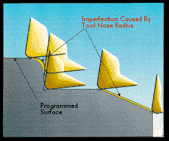
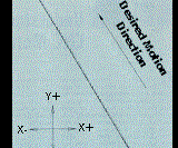
During linear interpolation commands, the control will precisely and automatically calculate a series of very tiny single axis departures, keeping the tool as close to the programmed linear path as possible. With today's CNC machine tools, it will appear that the machine is forming a perfectly straight line motion. However, Figure 1 shows what the CNC control is actually doing during linear interpolation.
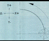
In similar fashion, many applications for CNC machine tools require that the machine be able to form circular motions. Applications for circular motions include forming radii on turned workpieces between faces and turns, and milling radii on contours on machining centers. This kind of motion requires circular interpolation. As with linear interpolation, the control will do its best to generate as close to a circular path as possible. Figure 2 shows what happens during circular interpolation.
Depending on the machine's application, you may find that you have other interpolation types available. Again, CNC control manufacturers try to make it as easy as possible to program their controls. For example, many machining center users perform thread milling operations on their machines. During thread milling, the machine must move in a circular manner along two axes (usually X and Y) at the same time a third axis (usually Z) moves in a linear manner. This allows the helix of the thread to be properly machined. This motion resembles a spiraling motion (though the radius of the spiral remains constant). Knowing that their customers need this type of motion for thread milling, CNC machining center control manufacturers offer the feature called helical interpolation.
Yet another type of interpolation may be required on turning centers that have live tooling. For turning centers that can rotate tools (like end mills) in the turret and have a C axis to rotate the workpiece held in the chuck, polar coordinate interpolation can be used to mill contours around the periphery of the workpiece. Polar coordinate interpolation allows the programmer to "flatten out" the rotary axis, treating it as a linear axis for the purpose of making motion commands.
The Three Most Basic Motion Types
While your particular CNC machine may have more motion types (depending on your application), let's concentrate on the three most common types available on almost all forms of CNC equipment. After briefly introducing each type of motion, we'll show an example program that stresses the use of all three.
These motion types share two things in common. First, they are all modal. This means they remain in effect until changed. If, for example, several motions of the same kind are to be given consecutively, the corresponding G code need only be specified in the first command.
Second, the end point of the motion is specified in each motion command. The current position of the machine will be taken as the starting point.
Rapid Motion (Also Called Positioning)
This motion type is used to command motion at the machine's fastest possible rate. It is used to minimize non-productive time during the machining cycle. Common uses for rapid motion include positioning the tool to and from cutting positions, moving to clear clamps and other obstructions, and in general, any non-cutting motion during the program.
You must check in the machine tool builder's manual to determine a machine's rapid rate. Usually this rate is extremely fast (some machines boast rapid rates of well over 1000 ipm!), meaning the operator must be cautious when verifying rapid motion commands. Fortunately, there is a way for the operator to override the rapid rate during program verification.
The command almost all CNC machines use to initiate rapid motion is G00. Within the G00 command, the end point for the motion is given.
Control manufacturers vary with regard to what actually happens if more than one axis is included in the rapid motion command. With most controls, the machine will move as fast as possible in all axes commanded. In this case, one axis will probably reach its destination point before the others. With this kind of rapid command, straight line movement will not occur during rapid and the programmer must be very careful if there are obstructions to avoid. With other controls, straight line motion will occur, even during rapid motion commands.
Straight Line Motion
This motion type allows the programmer to command perfectly straight line movements as discussed earlier during our discussion of linear interpolation. This motion type also allows the programmer to specify the motion rate (feed rate) to be used during the movement. Straight line motion can be used any time a straight cutting movement is required, including when drilling, turning a straight diameter, face or taper, and when milling straight surfaces.
The method by which feedrate is programmed varies from one machine type to the next. Generally speaking, machining centers only allow the feed rate to be specific in per-minute format (inches or millimeters per minute). Turning centers also allow feed rate to be specified in per-revolution format (inches or millimeters per revolution).
A G01 word is commonly used to specify straight line motion. Within the G01, the programmer will include the desired end point in each axis.
Circular Motion
This motion type causes the machine to make movements in the form of a circular path. As discussed earlier during our presentation of circular interpolation, this motion type is used to generate radii during machining. All feed rate related points made during our discussion of straight line motion still apply.
Two G codes are used with circular motion. G02 is commonly used to specify clockwise motion while G03 is used to specify counter clockwise motion. To evaluate which to use, you simply view the movement from the same perspective the machine will view the motion. For example, if making a circular motion in XY on a machining center, simply view the motion from the spindle's vantage point. If making a circular motion in XZ on a turning center, simply view the motion from above the spindle. In most cases, this is as simple as viewing the print from above.
Additionally, circular motion requires that, by one means or another, the programmer specify the radius of the arc to be generated. With newer CNC controls this is handled by an "R" word that simply states the radius. With older controls, directional vectors (specified by I, J, and K) tell the control the location of the arc's center point. Since controls vary with regard to how directional vectors are programmed, and since the R word is becoming more and more popular for radius designation, our examples will show the use of the R word. If you wish to learn more about directional vectors, refer to your control manufacturer's manual.
Example Program Showing Three Types Of Motion
In this particular example, we are milling around the outside of a workpiece contour. Notice that we are using a one-inch diameter end mill for machining the contour and we are programming the very center of the end mill. Later, during key concept number four, we will discuss a way to actually program the workpiece contour (not the cutter centerline path).
O0002 (Program number)
N005 G54 G90 S350 M03 (Select coordinate system, absolute mode, and start spindle CW at 350 RPM)
N010 G00 X-.625 Y-.25 (Rapid to point 1)
N015 G43 H01 Z-.25 (Instate tool length compensation, rapid tool down to work surface)
N020 G01 X5.25 F3.5 (Machine in straight motion to point 2)
N025 G03 X6.25 Y.75 R1.0 (CCW circular motion to point 3)
N030 G01 Y3.25 (Machine in straight motion to point 4)
N035 G03 X5.25 Y4.25 R1.0 (CCW circular motion to point 5)
N040 G01 X.75 (Machine in straight motion to point 6)
N045 G03 X-.25 Y3.25 R1.0 (CCW circular motion to point 7)
N050 G01 Y.75 (Machine in straight motion to point 8)
N055 G03 X.75 Y-.25 R1.0 (CCW circular motion to point 9)
N060 G00 Z.1 (Rapid away from workpiece in Z)
N065 G91 G28 Z0 (Go to the machine's reference point in Z)
N070 M30 (End of program)
While you may not understand all commands given in this program, concentrate on understanding what is happening in the motion commands (G00, G01, and G02/G03). With study, you should be able to see what is happening. Messages in parentheses are provided to document what is happening in each command.
Keep in mind that CNC controls do vary with regard to limitations with motion types. For example, some controls have strict rules governing how much of a full circle you are allowed to make within one circular command. Some require directional vectors for circular motion commands instead of allowing the "R" word. Some even incorporate automatic corner rounding and chamfering, minimizing the number of motion commands that must be given. Though you must be prepared for variations, and you must reference your control manufacturer's programming manual to find out more about your machine's motion commands, at least this presentation has shown you the basics of motion commands. You should be able to adapt to your particular machine and control with relative ease.
This is the third article in a 10 part series about the key concepts of CNC. To start at the beginning, read this article.
Next Article – Key Concept Number 4 - Understanding Motion Types
Related Content
6 Machine Shop Essentials to Stay Competitive
If you want to streamline production and be competitive in the industry, you will need far more than a standard three-axis CNC mill or two-axis CNC lathe and a few measuring tools.
Read More4 Commonly Misapplied CNC Features
Misapplication of these important CNC features will result in wasted time, wasted or duplicated effort and/or wasted material.
Read MoreHow to Mitigate Chatter to Boost Machining Rates
There are usually better solutions to chatter than just reducing the feed rate. Through vibration analysis, the chatter problem can be solved, enabling much higher metal removal rates, better quality and longer tool life.
Read MoreContinuous Improvement and New Functionality Are the Name of the Game
Mastercam 2025 incorporates big advancements and small — all based on customer feedback and the company’s commitment to keeping its signature product best in class.
Read MoreRead Next
Key CNC Concept #4—The Forms Of Compensation
Though applied for different reasons on different machine types, all forms of compensation allow the CNC user to allow for unpredictable conditions related to tooling.
Read MoreRegistration Now Open for the Precision Machining Technology Show (PMTS) 2025
The precision machining industry’s premier event returns to Cleveland, OH, April 1-3.
Read MoreBuilding Out a Foundation for Student Machinists
Autodesk and Haas have teamed up to produce an introductory course for students that covers the basics of CAD, CAM and CNC while providing them with a portfolio part.
Read More
.jpg;width=70;height=70;mode=crop)




.jpg;maxWidth=300;quality=90)


