
Integrating CMMs With Shopfloor Operations
A CMM on the shop floor combines the speed and flexibility of a CMM with the immediacy of shopfloor measurement.
Share


Coordinate measuring machines for shopfloor use are designed to resist the influence of ambient temperature on measurement results.
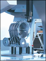
One advantage of a CMM over other gages is its efficiency at inspecting complex parts with multiple critical features. CMMs can be configured to handle a wide range of part sizes and shapes, eliminating the need for custom gaging.
The case for a shopfloor coordinate measuring machine combines the arguments in favor of shopfloor gaging with the case for a CMM in general. Measuring work on the shop floor can bring the application of the measurement closer to real time, so the results have more value in controlling the process. And compared with other measuring systems that can be used in manufacturing operations, the CMM offers the most flexibility. A CMM can accurately measure objects of widely varying sizes and geometric configurations, and it can describe the relationship between separate features of a workpiece. This flexibility, along with a CMM’s speed relative to surface plate techniques or fixed gages, allows measurement to be used cost effectively to refine the process and analyze process trends.
Integrating the speed, flexibility and accuracy of CMMs into shopfloor operations has been an ongoing trend. Shopfloor integration makes the measuring function integral to the machining process. The CMM may be physically attached, as in a transfer line, or it may be connected by some type of transfer mechanism, such as a cart or a rail-guided vehicle, that moves the work to the CMM from a machine tool.


Beyond the obvious benefit of real-time or close-to-real-time process control, integrated shopfloor gaging with a CMM has various advantages. On the shop floor, gaging is most often performed by machine tool operators themselves, reducing the need for special inspectors. Another benefit of shopfloor gaging is its ability to build a historical database that tracks the way machines, parts, pallets and fixtures have behaved during the actual machining process.
Capturing Time
An advantage of shopfloor gaging using a CMM is speed. Machined parts are becoming increasingly complex, with more measurement features and tighter tolerances. Meanwhile, high speed production to high standards of precision creates a demand for high inspection throughput.
The most dramatic advantage of the CMM is the increased inspection efficiency when compared with traditional surface plate/precision hand tool techniques. For example, measuring the location of a single hole using a surface plate and a height gage can involve:
- Squaring the face of the part with the surface plate.
- Indicating the top edge and bottom edge of the hole’s opening using a height gage.
- Comparing the measurements to a reference.
- Recording the readings.
- Calculating the difference between the measurements to find the location of the hole center line.
By contrast, measuring the same hole with a basic CMM involves:
- Automatically aligning the part with the CMM by measuring a datum plane, datum line and datum point. Approximate time: 30 seconds.
- Touching the hole in four locations. Approximate time: 8 seconds.
- Pressing the Print button to record the X location, Y location and diameter of the hole.
A part’s complexity further increases the inspection time for the operator using hand measurement tools. Because height gages and similar inspection tools only measure along a single axis, at least two setups are needed to locate details on the face of a workpiece. Even more setups may be needed to locate certain details. And when multiple sides of a part are checked, the setup has to be changed each time the part is rotated. The CMM, on the other hand, can measure multiple faces of a part without disturbing the setup.
Through faster measurements with fewer setups, inspection time can be reduced to as little as one-tenth of the time required using hand tool techniques. Ten parts can be inspected on a CMM in the same amount of time it takes to inspect one part using surface plate technology.
More sophisticated machines can reduce inspection time even more. The operator can be relieved of such time-consuming tasks as manually recording readings, checking the inspection sequence and performing computations. An additional benefit of the more advanced CMMs is their ability to measure arc lengths and profiles. These routines are literally impossible to perform using conventional inspection methods or even a manual CMM.
Countering Heat And Vibration
Building CMMs for shopfloor operations is a challenge. The effect of changing temperature on the measuring machine and the workpiece is the single most difficult obstacle to overcome.
One approach is to compensate for thermal expansion and thermal distortion errors by means of temperature sensors placed at critical points in the machine structure. Expansion and distortion values that are extrapolated from the sensor data are used to compensate each measured point, virtually canceling out the influence of temperature variations over a wide range.
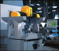
Another approach relates to the choice of materials in the CMM’s construction. For example, the design of Brown & Sharpe’s “One” shop-floor CMM is built around the use of steel bearings. All of the other components of the CMM have thermal properties similar to steel to minimize the effects of temperature variation on measurement accuracy. The X-axis carriage and Z-axis ram are constructed from an aluminum/silicon carbide matrix material that exhibits a similar coefficient of expansion to that of steel. At the same time, this material is light weight, allowing smaller motors to be used in the CMM, a change that further reduces the weight of the machine and also reduces the heat the machine generates.
Another challenge in placing precision CMMs on the shop floor is shielding them from vibration. The design of the One machine relies on a high-density polymer composite base to provide ten times more vibration damping than traditional materials. This base’s protection against vibration even extends to absorbing high-frequency noise.
Yet another design challenge that can’t be overlooked relates to software. Because of the need for greater accessibility when a CMM is used on the shop floor, software can play a role as important as that of the hardware. The software should allow operators of all skill levels to achieve accurate, repeatable inspection results. Brown & Sharpe’s software does this by including automated routines accessible using a graphic operator interface, as well as tutorial and on-board training modules covering topics before, during and after programming and data gathering. A special capability recognizes the type of feature being measured to create a graphical representation of this feature on the computer screen. The capability lets the operator rotate and enlarge a model of the inspected feature in order to see more clearly where the part is trending out of tolerance.
About the author: Christine L. Witkos is a product manager with Brown & Sharpe (North Kingstown, Rhode Island).


Related Content

4 Ways to Establish Machine Accuracy
Understanding all the things that contribute to a machine’s full potential accuracy will inform what to prioritize when fine-tuning the machine.
Read More
The Many Ways of Measuring Thickness
While it may seem to be a straightforward check, there are many approaches to measuring thickness that are determined by the requirements of the part.
Read More
Help Operators Understand Sizing Adjustments
Even when CNCs are equipped with automatic post-process gaging systems, there are always a few important adjustments that must be done manually. Don’t take operators understanding these adjustments for granted.
Read More
Choosing the Correct Gage Type for Groove Inspection
Grooves play a critical functional role for seal rings and retainer rings, so good gaging practices are a must.
Read MoreRead Next

5 Rules of Thumb for Buying CNC Machine Tools
Use these tips to carefully plan your machine tool purchases and to avoid regretting your decision later.
Read More
Building Out a Foundation for Student Machinists
Autodesk and Haas have teamed up to produce an introductory course for students that covers the basics of CAD, CAM and CNC while providing them with a portfolio part.
Read More
Setting Up the Building Blocks for a Digital Factory
Woodward Inc. spent over a year developing an API to connect machines to its digital factory. Caron Engineering’s MiConnect has cut most of this process while also granting the shop greater access to machine information.
Read More