Incorporating AFSD Into Hybrid Manufacturing Processes
Additive friction stir deposition (AFSD) is a new, solid-state additive manufacturing process that provides an alternative to beam-based AM processes.
Share


Hybrid manufacturing combines additive manufacturing (AM) to deposit a preform, metrology to determine the geometry of the printed preform and CNC machining to obtain the final part geometry, surface finish and tolerances.
Hybrid manufacturing process planning can include seven key steps:
- Digital part design
- Path planning for the AM process
- Metal deposition using AM to produce the preform
- Measuring the preform to determine its geometry and identify its coordinate system using available (for example, the edge of the build plate) or added (for example, tooling spheres) features or fiducials
- Path planning for CNC machining by importing the measured preform geometry and using it as the stock model with its predefined coordinate system
- CNC machining the preform to its design dimensions and surface finish using the coordinate system established by the fiducials
- Measuring the machined part to ensure conformance to design intent.
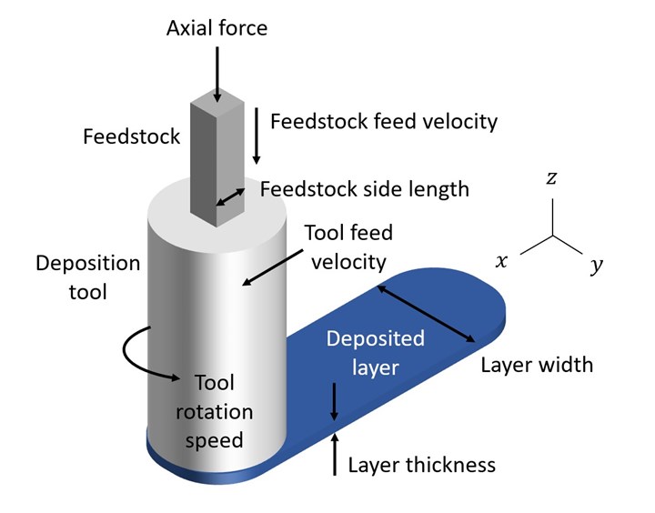
A new AM process is additive friction stir deposition (AFSD). AFSD is a solid-state AM process that provides an alternative to beam-based AM processes, which melt the material locally to obtain the desired near-net shape geometry. AFSD accomplishes solid-state deposition through plastic (permanent) deformation of a square cross-section, ductile metal alloy feedstock. A tool-spindle assembly containing a square bore constrains the feedstock as it is fed axially through the spindle and rotated against the build plate or previous layers. Spindle rotation provides heat generation through friction between the deposit and build surface and, subsequently, a reduction in the stress required to flow the material. The feedstock is deposited during movement of the tool at the selected tool feed velocity along the prescribed motion path. The feedstock feed velocity through the tool spindle is also specified. The combined tool rotation and feed motion enable layers to be bonded to the build plate and previous layers to deposit the desired preform geometry; see Figure 1.
Figure 1: AFSD where the feedstock is deposited in a layer-by-layer fashion to obtain metal preforms. Photo Credit: Tony Schmitz
To demonstrate hybrid manufacturing using AFSD, structured light scanning (to measure the preform geometry) and CNC machining, a hexagon-cylinder geometry was selected and a demonstration part was produced. AFSD was completed using a MELD Manufacturing L3 machine. As shown in Figure 1, 9.5-mm square metal feedstock was forced through a rotating spindle using a screw-type actuator located above the spindle.
The actuator enables rotation of the 0.5-m long feedstock with the spindle while simultaneously providing the axial force and material feed against the build plate or previous layer. The printed material is constrained axially by the gap between the rotating tool and build plate/previous layer (1 mm to 3 mm). Milling was completed using a Haas VF-4 three-axis CNC milling machine. Turning was completed using a Haas ST-15 CNC lathe. Structured light scanning was performed using a ZEISS/GOM ATOS Q.
The hexagon-cylinder processing sequence included a two-sided 6061 aluminum deposition and intermittent machining approach. The hexagon was deposited first on a square 25 mm thick, 6061 aluminum build plate. The origin was set at the build plate top corner for the helical interpolation tool path to generate the hexagon shape using a 2-mm layer height.
On the L3 machine, the spindle and edge finder were used to set the work coordinate system at the build plate top corner. Deposition then proceeded on the top surface of the build plate, which was clamped to the machine table using four toe clamps (one at each corner). The initial layer was deposited using a spindle speed of 300 RPM, material feed rate of 139.7 mm/min, and tool feed rate of 132.1 mm/min. Subsequent layers were deposited at 160 RPM with the same feed rates.
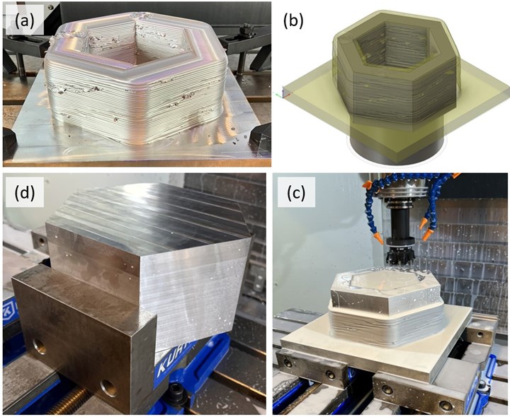
After deposition, the hexagon preform and build plate were scanned. Figure 2(a) displays the deposited hexagon. The part design and preform were then aligned using the origin at the build plate bottom corner and the milling tool paths were generated by CAM software with the imported scan used as the stock model; see Figure 2(b). The build plate was clamped in a pair of pre-aligned vises on the CNC milling machine table. The machine probing cycle was used to set the work coordinate system at the build plate bottom corner and the milling tool paths were completed to produce the desired hexagon geometry; see Figure 2(c).
Finally, the hexagon was inverted and the extra build plate material was machined away to obtain the final hexagon dimensions; see Figure 2(d). This inversion and machining step in a second vise setup motivated the location of the origin at the bottom of the build plate for the first setup. When turned over, the origin was located at the top of the part and could conveniently be identified using the machine probing cycle to set the new work coordinate system. Milling was completed using a spindle speed of 5,115 RPM with a roughing feed rate of 3,302 mm/min and finishing feed rate of 1,397 mm/min. These conditions were selected using tap testing and a corresponding stability map to select a spindle speed-depth of cut combination that was stable (for example, did not exhibit chatter). Flood coolant was applied.
Figure 2: (a) Hexagon preform after AFSD. (b) Alignment of scan and part design. The origin for both coordinate systems is the build plate corner for convenient identification on the CNC milling machine using the probe. (c) Milling the preform using two-vise setup. (d) Removing the build plate using a second vise setup where the part was inverted and clamped using opposing hexagon surfaces. The same origin was maintained throughout the production sequence.
Photo Credit: Tony Schmitz
Once the hexagon was complete, its base (the bottom of the original build plate) served as the build platform for the cylinder. The origin for the AFSD tool path planning was set at the center of the hexagon build plate surface, so this location was identified on the machine using the L3 spindle and edge finder. Deposition was completed using helical interpolation to generate the cylinder shape with a 2-mm layer height. The initial layer was deposited using a spindle speed of 275 RPM, material feed rate of 139.7 mm/min, and tool feed rate of 132.1 mm/min. Subsequent layers were deposited at 115 RPM with the same feed rates.
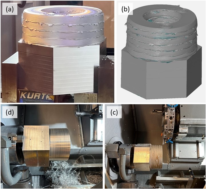
The cylinder preform is shown in Figure 3(a) and the corresponding scan is provided in Figure 3(b). By setting the scan (which served as the CAM stock model), design and toolpath coordinate systems at the center surface of the hexagon base, the lathe clamping requirement was simply to locate the part center on the spindle centerline.
This was accomplished by using the lathe’s three-jaw chuck to clamp three internal surfaces of the hexagon. This setup is shown in Figure 3(c) and the finished part is displayed in Figure 3(d). The facing, turning and boring operations were completed after touching off the hexagon base surface. The operating parameters were 243.84 m/min cutting speed, 0.89 mm roughing depth of cut, 0.25 mm/rev roughing feed rate, 0.13 mm finishing depth of cut and 0.051 mm/rev finishing feed rate. The carbide insert nose radius was 0.40 mm.
Figure 3: (a) Cylinder preform on hexagon base. (b) Scan of part after cylinder deposition. (c) Part clamped in lathe using three-jaw chuck on internal surfaces of hexagon. (d) Finished part before removal from lathe. Photo Credit: Tony Schmitz
This part demonstrated the combination of AFSD, turning, milling and structured light scanning in a hybrid manufacturing scenario. Structured light scanning was used to generate stock models for tool path generation that incorporated coordinate systems that could be realized physically on the machining systems. The hexagon-cylinder geometry was fabricated using intermittent deposition and machining operations. The coordinate systems for the two-sided part (deposition was completed on both surfaces of the original build plate) were connected using structured light scanning and origins that could be identified on the machining systems using standard probing routines. Both turning and milling operations were used to produce the final geometry and surface finish.
Read Next
Registration Now Open for the Precision Machining Technology Show (PMTS) 2025
The precision machining industry’s premier event returns to Cleveland, OH, April 1-3.
Read MoreBuilding Out a Foundation for Student Machinists
Autodesk and Haas have teamed up to produce an introductory course for students that covers the basics of CAD, CAM and CNC while providing them with a portfolio part.
Read More5 Rules of Thumb for Buying CNC Machine Tools
Use these tips to carefully plan your machine tool purchases and to avoid regretting your decision later.
Read More


