
How to Improve Comparator Stand Performance for Gaging
Adding digital display systems and high-precision probes to comparator stands brings new functionality and pitfalls. The right setup can minimize errors.

Share


ECi Software Solutions, Inc.
Featured Content
View More

Hwacheon Machinery America, Inc.
Featured Content
View More


.png;maxWidth=45;format=webp)
DMG MORI - Cincinnati
Featured Content
View More

Takumi USA
Featured Content
View More


Digital display systems with high-resolution probes have advanced to a state where they can bring sub-micron performance to the point of manufacture at a cost that is not much higher than the price of a good digital indicator. Today’s probe and amplifier systems are designed with the protection required to be used in the production environment. The specs of the systems are outstanding — much better than most digital indicators.
These electronic measuring systems can have the most benefit for use on mechanical comparator stands. Since most high-performance displays and probes are used over a short range, the most applicable use is in a comparative stand. The fundamental nature of these stands is to have a setting master in which the part being inspected is compared to. However, a closer look needs to be given to the comparator stand when upgraded with a high-performance display and probe. Mechanical errors within the stand will now be magnified significantly. What was once deemed a reliable measuring station may appear a little shaky in its performance. Let’s look at ways to improve comparator stand performance.


As one would expect when it comes to precision, comparator system robustness is a good place to start. Just look at precision length systems found in the calibration room. The rule is often that bigger is better, in the name of rigidity and stability. While bench stands used in the shop are not going to be called upon to make this level of analysis, the concept is the same. The more robust the stand, the better performance it is apt to give.
All images courtesy of George Schuetz
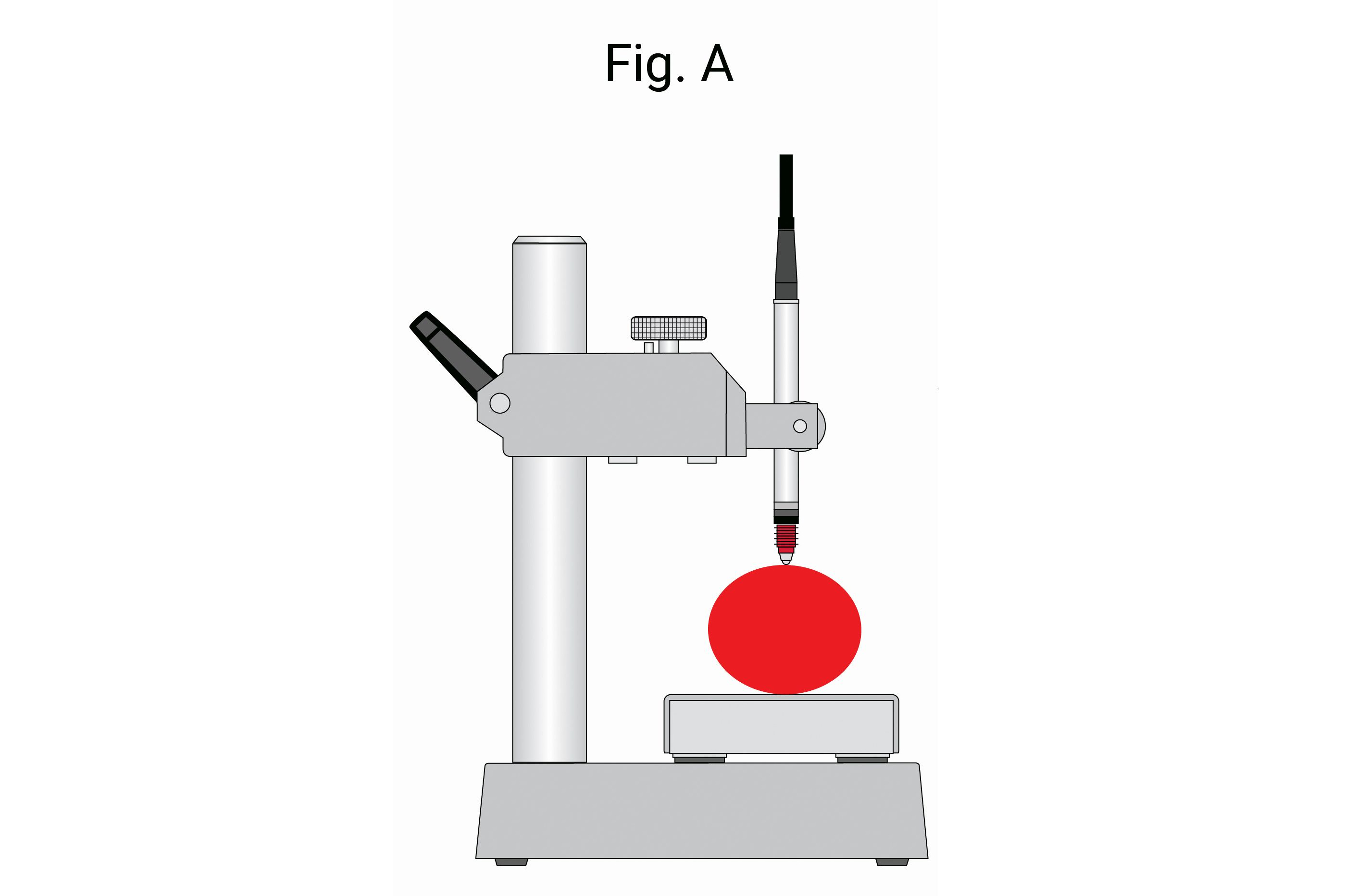
Probably the most practical comparative gage is seen in Fig. A. It offers an interchangeable platen, a long post with an adjustable arm over its full length and a fine adjustment mechanism to set the probe to the nominal position. This stand offers great flexibility for a variety of setups. However, with great flexibility comes a source of error (as the word “flex” implies), because each one of these joints (or connections) is a possible source of looseness. With looseness comes repeat errors that can be shown on the high-resolution display.
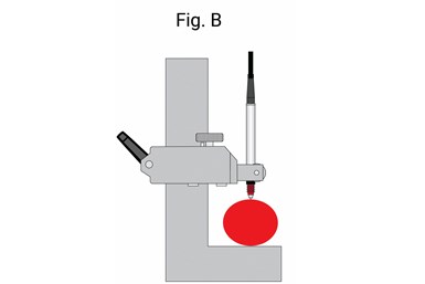
By eliminating the points of concern and making minor changes, gaging performance will improve. In Fig. B, we have made the base and the post into one piece, eliminating two contention points: the moveable anvil and the post connection. This configuration still allows a longer adjustment to accommodate different sizes and fine adjustment of the probe. These are two key factors when a wide range of parts need to be checked.
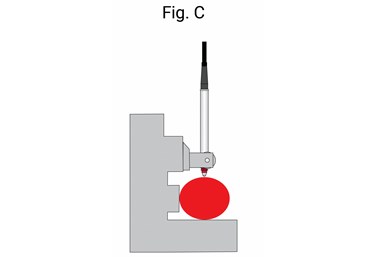
The higher the resolution, the more critical part positioning becomes. In Fig. C, two changes have been made. First, the long-range adjustment has been removed with the retention of the fine adjustment for probe positioning, and a backstop has been added. When mastering any comparative instrument, it is best to master with the same shape master as the part. Adding the backstop ensures the master and the part are positioned at nearly the same location. This arrangement offers only one adjustment point: the fine adjustment to further eliminate loose potentials. The addition of the backstop for more repeatable master and part positioning is a significant improvement.
In Fig. D, we have made the stand for the particular size being measured. It is a fixed comparative gage, offering the highest performance for making
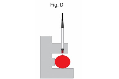
comparative readings. This offers the best opportunity for the most accurate and repeatable results. The only issue that comes to mind with this type of gage is that it is primarily useful in a bench gaging operation. It relies on gravity to hold the part in position. If used as a portable gage, the operator would have to ensure the gage is carefully loaded on the part, so it rests securely on the anvil and the backstop. As one can imagine, this inserts another source of error — the user. Human nature is known to be a large source of measurement errors.
Finally, the solution shown in Fig. E offers the best fit for applications where
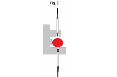
bringing the gage to the part is required. This is the concept that most air or electronic snap gages are built to as they are made to the specific dimension to be measured and employ differential gaging. Differential gaging allows for high-performance length measurement while compensating for a slight shift in line positioning of the part. With these fixed-size variable gages, all the operator must do is ensure the part is locked in against the backstop so the true diameter of the part is displayed as compared to the master.
Adding high-precision resolution, display and probe systems to existing gaging is a logical way to attempt to get more precision from existing gaging. However, it is important to understand that there may be obstacles in the existing gaging that will limit its performance.


Related Content

Parts and Programs: Setup for Success
Tips for program and work setups that can simplify adjustments and troubleshooting.
Read More
Turning Fixed-Body Plug Gages Inside Out
Fixed-body mechanical plug gages provide fast, high-performance measurement for tight-tolerance holes.
Read More
Help Operators Understand Sizing Adjustments
Even when CNCs are equipped with automatic post-process gaging systems, there are always a few important adjustments that must be done manually. Don’t take operators understanding these adjustments for granted.
Read More
Orthopedic Event Discusses Manufacturing Strategies
At the seminar, representatives from multiple companies discussed strategies for making orthopedic devices accurately and efficiently.
Read MoreRead Next

Registration Now Open for the Precision Machining Technology Show (PMTS) 2025
The precision machining industry’s premier event returns to Cleveland, OH, April 1-3.
Read More
5 Rules of Thumb for Buying CNC Machine Tools
Use these tips to carefully plan your machine tool purchases and to avoid regretting your decision later.
Read More
Building Out a Foundation for Student Machinists
Autodesk and Haas have teamed up to produce an introductory course for students that covers the basics of CAD, CAM and CNC while providing them with a portfolio part.
Read More