How Accurate Is Your Machining Center?
Virtually every machine tool builder lists, as part of a machine's specification, accuracy and repeatability figures. What's generally not given is the method used to arrive at the figures. Though these methods are defined in linear positioning standards, not all builders use the same standards.
Share


There are several positioning standards that provide methods by which an accuracy or repeatability specification can be determined. The same machine tool will give different accuracy and repeatability numbers depending on the standard used. This makes comparison shopping between various machine tools difficult.
This article compares six of the most common linear positioning standards used by the machine tool industry, in the United States, Europe and Asia to qualify machining centers. The standards that will be compared are:
NMTBA (United States), ISO 230-2 (Europe), BSI BS 4656 Part 16 (British), VDI/DGQ 3441 (German), JIS B 6336-1986 (Japanese), and ASME B5.54-92 (USA).
But before getting into a comparison of these standards, it's necessary to define some critical terminology. Defining these terms permits discussion from a common frame of reference.
What Is Accuracy?
Most of us have, at one time or another, shot a gun or bow, or thrown a dart. In each case we were trying to hit a target, preferably the bull's-eye. If we fire six times at the target bull's-eye and hit it every time, we have very good aim—we are accurate. The bull's-eye would probably look like Figure 1.
This same analogy applies to machine tools. Both the machine builder and user want the machine slide to hit that target bull's-eye every time it's moved. But the machine sometimes has different ideas. An accuracy spec quantifies how well we hit the target. Each linear positioning standard defines a method for determining accuracy and other specifications on a consistent basis.
Machine tool builders talk about three kinds of accuracy: unidirectional forward, unidirectional reverse and bidirectional. Let's say you were in a contest where you had to walk toward a target while shooting and then shoot at the same target while walking away from it. The accuracy while walking toward the target would be unidirectional forward accuracy and that walking away from the target is unidirectional reverse. Each of these are scored individually. You can also score the overall accuracy forward and reverse. This is called bidirectional accuracy because it takes both directions into account.
Machine tool builders can describe accuracy with terms like error-band, accuracy, positional deviation, position uncertainty and mean-to-mean accuracy. Each of these terms is calculated differently.
What Is Repeatability?
If we look again at Figure 1, the distance between each hit illustrates repeatability. We know they are all in the bull's-eye but chances are the person firing the gun wavered slightly or was just a fraction of an inch off when sighting, causing the bullets to hit not one on top of the other, which would be perfect repeatability, but rather in a pattern shown in Figure 1. This pattern is repeatability. Machine tool slides also vary about the target point. Here's another example of accuracy and repeatability.
Figure 2 shows a very tight pattern. Therefore, the repeatability is very good. Even so, the person must have pulled left every time he/she fired, or maybe the rifle sight was off to the left slightly. The result is poor accuracy. Remember the bull's-eye is still the target.
We can enter the same contest of shooting at a target while walking toward it and away from it. Walking toward the target we get a pattern of holes perhaps like Figure 3. This represents forward repeatability.
Walking away from the target we may get a pattern like Figure 4. This illustrates reverse repeatability.
Repeatability is tested as the total range, so if the bottom bullet hole and the top bullet hole are 0.5 inch apart, then this figure represents the repeatability. There is also a bidirectional repeatability which takes into account both Figures 3 and 4, and as a value would be the distance from the bottom bullet hole on Figure 4 to the top hole on Figure 3.
Transferring this comparison to a machine tool, we have six targets for each machine slide. We position to these targets from both directions seven times and from this information we derive repeatability.
Repeatability may be described by terms such as forward repeatability, reverse repeatability, bidirectional repeatability, and positional scatter. Each of these terms is calculated differently.
Lost Motion
Lost motion means motion is initiated but you don't see any results until all the lost motion is accounted for—like taking up slack on a block and tackle. If you look closely at Figures 3 and 4 you will notice our marksman has lost motion. In Figure 3, all the bullets are left of center, and in Figure 4 they are right of center. The difference between them is lost motion. Other lost motion terms are reversal error, and mean reversal error.
Now assume we have six targets, and position to each target seven times. We position from an arbitrary starting point—let's call it zero. If we position to six targets, turn around and position to the same six targets on our way back to zero, save all the errors at each target point, then repeat this seven times, we have 84 pieces of data. Figure 5 will give you the general idea of the normal collection process for these data.
From this data accuracy, repeatability, and lost motion specifications are calculated.
Sigma
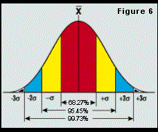
But before we calculate any of these values, we must talk about sigma. It's represented by the Greek letter s or S. Sigma is also known as Standard Deviation. Standard deviation is normally shown using a bell shaped curve as shown in Figure 6 (at right).
On each side of center (x) is 3s, which is three times one sigma.
As you can see, on the bell curve, ± 1 sigma covers about 68 percent of the area under the curve. ±2 sigma covers 95 percent and ±3 sigma covers 99.7 percent. If we position to our six targets seven times each, calculate the standard deviation, and multiply it by six, then 997 times out of 1,000, we would hit our six targets within that value.
The same raw data was used for all six comparisons. This data is in the inch system of measurement and all values are in microinches (millionths of an inch). So, for example a measurement of 982 as indicated on the chart would be 0.000982 or 982 millionths of an inch.
What's It Mean?
All the standards except JIS output total bandwidth for the values, even though many builders advertise ± values regardless of which standard is used. This may render the appearance of a lower number.
NMTBA is the only standard that statistically calculates using bidirectional data. The other statistical standards generate their bidirectional data from the individual forward and reverse information only. This is not necessarily better or worse than NMTBA, but it definitely does result in smaller figures, which can unfairly impact a prospective customer's spreadsheet. The fact is that NMTBA is the most stringent.
ASME B5.54-92 is really the "new kid on the block," but has quickly become the new national standard of the United States, replacing the statistical NMTBA in many arenas. However, each standard has its place depending on your taste for either statistical data or actual raw data.
In summary, any of the standards described may be used to evaluate a machine tool's linear positioning. However, we must be aware that one standard can allow the machine to appear to be more accurate than it will be when evaluated using another standard.
About the authors: Steven Klabunde is vice president of corporate technology and Ronald Schmidt is quality assurance test engineer for Giddings & Lewis, Fond du Lac, Wisconsin.
Related Content
The Link Between CNC Process Control and Powertrain Warranties
Ever since inventing the touch-trigger probe in 1972, Sir David McMurtry and his company Renishaw have been focused on achieving process control over its own manufacturing operations. That journey has had sweeping consequences for manufacturing at large.
Read MoreProcess Control — Leveraging Machine Shop Connectivity in Real Time
Renishaw Central, the company’s new end-to-end process control software, offers a new methodology for producing families of parts through actionable data.
Read More4 Ways to Establish Machine Accuracy
Understanding all the things that contribute to a machine’s full potential accuracy will inform what to prioritize when fine-tuning the machine.
Read MoreBallbar Testing Benefits Low-Volume Manufacturing
Thanks to ballbar testing with a Renishaw QC20-W, the Autodesk Technology Centers now have more confidence in their machine tools.
Read MoreRead Next
Registration Now Open for the Precision Machining Technology Show (PMTS) 2025
The precision machining industry’s premier event returns to Cleveland, OH, April 1-3.
Read MoreSetting Up the Building Blocks for a Digital Factory
Woodward Inc. spent over a year developing an API to connect machines to its digital factory. Caron Engineering’s MiConnect has cut most of this process while also granting the shop greater access to machine information.
Read More5 Rules of Thumb for Buying CNC Machine Tools
Use these tips to carefully plan your machine tool purchases and to avoid regretting your decision later.
Read More







.jpg;maxWidth=300;quality=90)


