Find The Right Speed For Chatter-Free Milling
It used to be that a little chatter was easy to forgive. Not anymore. In shops aiming to minimize hand finishing, machined surfaces have to be smooth. And in high speed machining applications, chatter itself can set the speed limit.
Share


It used to be that a little chatter was easy to forgive. Not anymore. In shops aiming to minimize hand finishing, machined surfaces have to be smooth. And in high speed machining applications, chatter itself can set the speed limit. The kind of excessive chatter that high spindle speeds can bring about can drastically erode the life of a carbide tool, or make it impossible to mill a thin wall or some other delicate feature accurately. But even so, reducing this chatter is not necessarily a matter of slowing down.
Rather, it’s a matter of finding just the right speed. Particularly at high rpm, chatter is influenced by the harmonic characteristics of the cut. The machine tool, tooling, workpiece, and workholding together all sum to produce a complex dynamic system. And this system is likely to have a variety of low-chatter zones occurring at different spots along the spindle speed range. Low-chatter rpm values may occur at lower speeds, but they may also occur at higher speeds. In addition, chatter theory predicts that these regions of stability get larger at the higher values of rpm.
Long-time machinists know this intuitively. An experienced machinist tweaking the speed override may not always turn it down. Instead, he may turn the speed up slightly in search of a "sweet spot" where the cut sounds better.
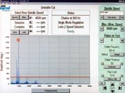
The system (which the company calls "Harmonizer") consists of a microphone that connects to a PC, a hardware key and vibration analysis software. This last component is based on a chatter control algorithm from Manufacturing Laboratories, Inc. (Gainesville, Florida).
How the system works is straightforward. The user enters some basic data about the cut the system is about to hear, including spindle speed and the number of flutes on the tool. Then the user records a sample of cutting sound. Based on this information, the software recommends a spindle rpm that falls within a stable speed range. The approach is already being used by a major manufacturer to find optimum milling speeds for high speed machining. (See the "Learn More" Box at the top of this article.)
There are some limitations. One is that not all types of metalcutting are appropriate. The system was designed specifically for intermittent cutting operations—milling in particular. Another limitation is that the system can’t address all forms of vibration. Unbalanced tooling and/or a loose fixture, for example, can result in a forced vibration that doesn’t necessarily respond to any optimal spindle speed. Instead, the software’s rpm recommendations apply only to chatter—defined as a self-excited vibration.
Reducing this chatter can bring about not only longer tool life and a higher quality part, but also higher productivity. More stable milling may make it possible to increase the depth of cut. Thus, even if the "sweet spot" rpm is a little lower than what the machine and cutting tool could achieve if more chatter were permitted, cutting at this lower speed may bring about the highest practical rate of metal removal. MMS
Related Content
-
How to Accelerate Robotic Deburring & Automated Material Removal
Pairing automation with air-driven motors that push cutting tool speeds up to 65,000 RPM with no duty cycle can dramatically improve throughput and improve finishing.


