Cutting To The Model
This mold shop's cutting tool strategies help it eliminate hand spotting altogether by machining complex molds directly to the CAD model.
Share


Takumi USA
Featured Content
View MoreMold shops refer to the concept of machining to zero stock in different ways. Steve Rotman, president of Ameritech Die and Mold, calls it “cutting to the model.” For Mr. Rotman, the concept:
--eliminates hand spotting after machining;
--enables quick design changes, because location of all mold surfaces is known;
--provides effective mold venting without milling to negative stock; and
--allows 100 percent shutoff with full contact between mold surfaces at the parting line.
In simplest terms, Ameritech adopted the cut-to-the-model mindset to provide to its customers the highest quality injection, compression and blow molds it could build.
As with any hard milling work, basic elements are required to successfully machine blocks that may be as hard as 58 Rc to the mold’s CAD model. A rigid machine tool is essential for both roughing and finishing operations. Some shops standardize on a single machine tool manufacturer. Ameritech hasn’t. It uses CNC machines from Enshu, Kuraki, Makino and OKK. Much of the finish machining is done on a Fidia K165 3 + 2 VMC that has a 30,000-rpm spindle. Ameritech also uses a couple of different CAM packages, too—Surfcam for 2D work and Cimatron for creating three-axis tool paths.
In order to minimize runout and the risk of chatter, many shops, including Ameritech, use an HSK interface and pre-balanced hydraulic or shrink-fit toolholders. Maximum acceptable tool runout at Ameritech is 0.0002 inch. Balancing is especially critical when using small-diameter ballnose end mills that operate at very high spindle speeds. Ameritech uses cutters with diameters as small as 0.015 inch for finishing operations.
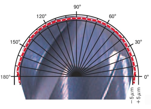
All of these elements, combined with smart application of finishing cutters that have a radius accuracy of ±0.0002 inch, allow the company to machine molds that are accurate to the model by ±0.0005 inch. Mr. Rotman and a couple of his deft young machinists/programmers shared some cut-to-the-model cutting tool insight during a recent visit to their Mooresville, North Carolina shop.
Applying Leading Technologies
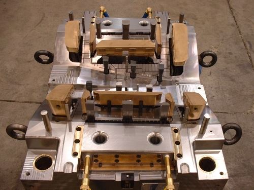
Ameritech specializes in building and repairing large, complex molds, most commonly for the automotive industry. Its niche is creating molds for airbag covers for Tier One suppliers. These molds—as much works of art as they are precision tooling—use choreographed movement of accurately machined lifters and slides to create the various undercuts and slots those plastic parts require.
Very soon after opening in 1985, Ameritech acquired its first CNC machine—an Enshu VMC that is still used to mill some small mold components. This purchase laid the foundation for the company’s philosophy of integrating high-technology equipment to support the cutting-to-the-model principle. The self-sufficient shop now has a graphite mill, gundrill, microwelder, sinker and wire EDM, and two injection molding machines (IMMs). The 220-ton and 460-ton IMMs are used to run-off of some molds.
The facility’s center corridor is home to the 2D machining bay. This bay produces components that include mold bases and mold, ejector, backup and clamp plates. The machine tools in this bay are also used to rough cavity and core blocks before delivery to the 3D bay for semi-finishing and finishing operations.
Ameritech’s machinists are also CAM programmers. Mr. Rotman feels that by combining these duties, the employees have an inherent sense of process ownership and adherence to quality. With each new job, the shop involves machinists early in the design phase so that they can offer input as to how best to design the mold to facilitate the machining work. By the time the job gets to the floor, the machinists have familiarized themselves with the mold design and can start programming and machining straightaway.
What is particularly evident at Ameritech is the enthusiasm that the relatively young group of shop employees (average age is 31) brings to the cut-to-the-model concept, especially when it comes to getting the most out of precision cutting tools. Many of the 25 employees are graduates of the company’s innovative apprenticeship program. They have an innate willingness to try different strategies and techniques to machine mold components. This is in part because they never had a chance to develop “bad habits” in shops that don’t cut to the model.
The Cutter’s Role
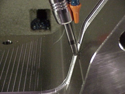
Recently, Ameritech has started using Miracle Nova ballnose end mills from Mitsubishi Materials (Irvine, California). Although these two-flute solid carbide finishing cutters cost more than less-accurate cutters, the pay-off comes from their precision. These cutters have a proprietary AlTiN coating and tight ball radius accuracy of ±0.0002 inch. In addition, their center tip geometry extends tool life, notes Matt Goins, the machinist/programmer who performs most of the finishing work on the Fidia VMC. The center of a ballnose end mill tip is effectively a dead spot, so it tends to rub and wear quickly, causing a poor surface finish. Because the Miracle tools are ground to provide a minimum of web thickness at the tip, the rate of wear is reduced and chip evacuation improves, Mr. Goins says.
Ameritech’s strategy for stock removal during semi-finishing and finishing differs from other shops that cut to zero, Mr. Rotman notes. The company typically roughs to 0.025 inch of size. It then takes two semi-finishing passes, stepping down to 0.01 inch and then to 0.002 inch of the model. A subsequent pass with the finishing cutter brings the mold to the model.
The two semi-finishing passes do prolong machining time versus shops that take a single semi-finishing pass to 0.005 inch before finishing. However, Mr. Rotman says the extra pass offers better performance and longer life for the finishing cutter. Because there is less cutting pressure when removing 0.002 inch versus 0.005 inch during finishing, there is less chance that the cutter will deflect. In addition, removing only 0.002 inch on the finish pass extends the life of a high-end finish cutter because it encounters less stock. Mr. Goins says he has achieved 40 hours of cutting with a single finish cutter using this step-down technique, typically finishing at 150 ipm and between 18,000 rpm and 30,000 rpm, depending on the cutter’s diameter. The stepover will typically be the same as the cutter’s chip load per tooth to deliver a quality surface finish. He’ll reduce speeds, feeds and stepover accordingly when using cutters that have very small diameters.
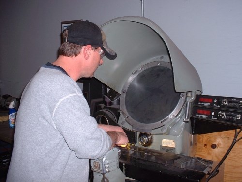
The finishing cutter doubles as a quality gage for machined surfaces. By using a magnifying glass or shadow graph to examine cutter condition after machining, the machinist can tell if the mold was machined to size. If no wear is evident, then the mold has been successfully cut to the model and measurement isn’t necessary. Each mold is blued after assembly, however, to verify that all mold surfaces are making proper contact.
If it appears that a cutter won’t last an entire finishing operation, it will be replaced. Worn finish cutters aren’t trashed, though. Oftentimes they will be used for less-accurate semi-finishing work, further extending the usefulness of a costly tool. The shop has also used cutters that have had their tips worn down to the substrate to machine vertical or angled walls using the side of the tool.
Mike Busby, machinist/programmer in the 2D bay, often uses four-flute cutters designed to machine at low speeds and high feed rates when roughing blocks. For example, he may run a 2-inch indexable insert shell mill at a speed of only 1,200 rpm but a feed rate of 250 ipm. The depth of cut would be 0.03 inch and stepover would be 0.6 times the cutter’s diameter. When cutting 3D surfaces with the side of a four-flute ballnose end mill, however, he says he often pushes the cutter to machine at 300 ipm and 15,000 rpm.
As is often the case with hard milling operations, both roughing and finishing are performed dry using air blast to assist in chip evacuation. The goal is to take light, quick cuts so that all the heat generated during the cut comes out with the chip to avoid warping the block. Dark-purple chips provide evidence that this is occurring. In some cases, especially when using very small cutters, an oil-based mist is used. The oil mist is not used for its cooling effect, but rather to provide lubrication for improved cutting action.
The shop is also mindful of facility and machine tool temperature. Air conditioning helps control the building’s ambient temperature so that fluctuations don’t adversely affect machining accuracy. Some finish milling is performed overnight to further reduce the chance of temperature fluctuation. In addition, a cold machine will be dry-cycled for at least 30 minutes after start-up to ensure that its spindle, ballscrews, ways and other critical components are warm before cutting.
A Different Moldmaking Mindset
Mr. Rotman began his moldmaking career at a shop that didn’t cut to the model. That shop machined the cavity close to size, but made sure to leave extra stock in potential problem areas for fear of rewelding and remachining. It machined the core approximately 0.01 inch undersize for subsequent hand spotting. The shop’s machining philosophy was to get components on and off a machine tool as quickly as possible. Now that he has his own shop, Mr. Rotman chooses to take extra time and care machining molds to the model to eliminate hand spotting altogether.
Related Content
How to Accelerate Robotic Deburring & Automated Material Removal
Pairing automation with air-driven motors that push cutting tool speeds up to 65,000 RPM with no duty cycle can dramatically improve throughput and improve finishing.
Read MoreRead Next
Registration Now Open for the Precision Machining Technology Show (PMTS) 2025
The precision machining industry’s premier event returns to Cleveland, OH, April 1-3.
Read More5 Rules of Thumb for Buying CNC Machine Tools
Use these tips to carefully plan your machine tool purchases and to avoid regretting your decision later.
Read More




.jpg;maxWidth=300;quality=90)


