10 Tips for Titanium
Simple process considerations can increase your productivity in milling titanium alloys.
Share


Titanium alloys and aluminum alloys are alike in the following ways: Both types of metals are used to make aircraft structural components, and in both cases, the component could require 90 percent of the material to be milled away before the part is complete.
Plenty of shops probably wish the metals had more in common than this. Aircraft-industry suppliers that are comfortable machining aluminum are finding themselves machining much more titanium because newer aircraft designs make increased use of the latter metal.
John Palmer, global aerospace segment manager for cutting tool maker Stellram, says many of these shops actually have more titanium machining capacity than they realize. Many valuable techniques for machining titanium effectively are not difficult to employ, but few shops use all of the techniques that are available for milling this metal productively. He consults with manufacturers about methods for improving milling performance in various aerospace alloys, titanium alloys included. He says titanium does not have to be difficult—it’s just that the entire machining process has to be considered, because any one element could impede the overall process’s effectiveness.
Stability is key, he says. When the tool touches the workpiece, it closes a circle. The tool, toolholder, spindle, column, ways, table, fixturing and workpiece are all part of that circle, and part of the needed stability. Other important considerations include coolant pressure and volume, as well as the method of coolant delivery, plus methodology and application—the focus of this article. To realize more of the potential of those processes that do have the potential to machine titanium productively, Mr. Palmer often shares advice including all of the following tips:
1. Keep Radial Engagement Low
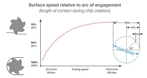
One of the crucial challenges of titanium is heat dissipation. In this metal, relatively little of the heat generated during the machining operation is ejected with the chip. Compared to machining other metals, a larger percentage of the heat in a titanium machining process instead goes into the tool. Because of this effect, the choice of radial engagement dictates the choice of surface speed in this metal.
The graph in Figure 1 shows this. Full slotting—meaning 180-degree engagement—demands a relatively low surface speed. But reducing the radial engagement reduces the time the cutting edge generates heat, and allows more time for the cutting edge to cool before entering the material on the next rotation. Thus, as radial engagement is reduced, the surface speed can be increased while maintaining the temperature at the cut point. For finishing, a milling process consisting of a very small arc of contact with a sharp, honed cutting edge and a high surface speed and minimal feed per tooth can realize exceptional results.
2. Increase Flute Quantity
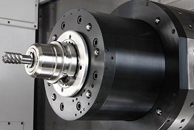
Commonly used end mills have four or six flutes. In titanium, this might be too few. The more effective number of flutes could be ten or more (see Figure 2).
Increasing the number of flutes compensates for the need for a low feed per tooth. The close flute spacing of a 10-flute tool is too tight for chip clearance in many applications. However, productive milling of titanium already favors a low radial depth (see tip #1). The small chip resulting from this leaves open the freedom to use a high-flute-count end mill to increase productivity.
3. Make a Thick-to-Thin Chip
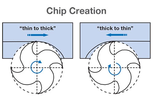
“Climb milling” is the familiar term for this idea. That is, do not feed the milling cutter so that the edge moves through the material in the same direction that the tool is feeding. Known as “conventional milling,” this approach to machining causes the chip to start thin and become thicker. As the tool impacts the material, friction forces create heat before the material starts to shear away from the parent metal. A thin chip is unable to absorb and eject this generated heat, which instead goes into the cutting tool. Then, at the exit point where the chip is thick, increased cutting pressure makes chip adhesion a danger.
Climb milling—or thick-to-thin chip formation—starts with the cutting edge entering the excess material and exiting on the finished surface (see Figure 3). On side milling, the tool tries to “climb over” the material, creating a thick chip on entry for maximum heat absorption and a thin chip on exit to prevent chip adhesion.
Contour surface milling demands close examination of the tool path to ensure that the tool continues to enter on the excess material and exit on the finished surface in this way. Achieving this during intricate passes is not always as simple as merely keeping the material to the right.
4. Arc In
In titanium and other metals, tool life is lost in moments of jarring change in force. The worst of these moments often occurs when the tool enters the material. Directly feeding into the stock (as almost any standard tool path would do) produces an effect similar to hitting the cutting edge with a hammer.
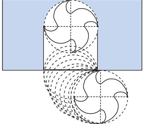
Glide in softly instead. To do this, create a tool path that arcs the tool into the material instead of entering it in a straight line (see Figure 4). In thick-to-thin milling, the arc of toolpath entry should follow the same direction (clockwise or counterclockwise) as the rotation of the tool. The arcing entry path allows for a gradual increase in cutting force, preventing snatching or tool instability. Heat generation and chip creation also increase gradually until the tool is fully engaged in the cut.
5. End on a Chamfer
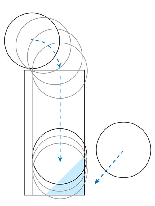
Jarring changes in force can occur at the tool exit as well. As useful as thick-to-thin cutting is (tip #3), the problem with this method is that the thick-to-thin formation suddenly stops as the tool reaches the end of the pass and starts to clear the metal. The abrupt change produces a similarly abrupt change in force, shocking the tool and perhaps marring the part surface. To prevent the transition from being so sudden, take the precaution of first milling a 45-degree chamfer at the end of the pass so that the tool sees a gradual decline in its radial depth of cut (see Figure 5).
6. Rely on Secondary Relief
A sharp cutting edge minimizes cutting forces in titanium, but the cutting edge also needs to be strong enough to resist cutting pressure. A secondary-relief tool design, in which the first positive area of the cutting edge resists forces, after which the second area falls away to increase clearance, accomplishes both these objectives (see Figure 6). Secondary relief is common in tooling, but in titanium in particular, experimenting with tools having different secondary-relief designs might reveal surprising changes in cutting performance or tool life.
7. Alter the Axial Depth
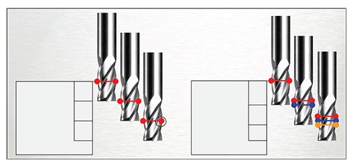
At the depth of cut, oxidation and chemical reaction can affect the tool. Early damage can occur at this one spot if the tool is repeatedly used at the same depth. When taking successive axial cuts, this damaged area of the tool can cause work hardening, as well as lines on the part that are unacceptable for aerospace components, meaning this effect on the surface can necessitate an early tool change. To prevent this, safeguard the tool by changing the axial depth of cut for each pass, distributing the problem area to different points along the flute (see Figure 7). In turning, a similar result can be achieved by taper turning the first pass and parallel turning the subsequent pass, preventing depth-of-cut notching.
8. Limit the Axial Depth Around Slender Features
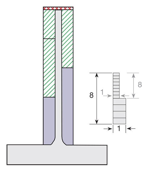
The ratio 8:1 is useful to remember when milling thin walls and unsupported features in titanium. To avoid deflection of pocket walls, mill these walls in successive axial stages instead of milling to the entire wall depth with one pass of an end mill. Specifically, the axial depth of cut at each step down should not be greater than 8 times the thickness of the wall that will be left behind after these milling passes are performed (see Figure 8). If the wall is 0.1 inch thick, for example, the axial depth of cut for a milling pass adjacent to it should be no more than 0.8 inch.
Despite the depth limit, it’s possible to work this rule so that productive milling is still possible. To do this, machine thin walls so that an envelope of rough stock remains around the wall, making the feature 3 or 4 times thicker than the final feature. If the wall is held to 0.3-inch thick, for example, then the 8:1 rule allows an axial depth of 2.4 inch. Following these passes, take lighter axial depths to machine the thick walls down to their final dimension.
9. Choose a Tool Much Smaller than the Pocket
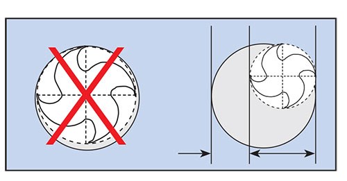
Because of the extent to which the tool absorbs heat in titanium, the tool needs clearance to allow for cooling. When milling a small pocket, the diameter of the tool should be no more than 70 percent of the diameter (or comparable dimension) of the pocket (see Figure 9). Less clearance than this risks essentially insulating the tool from coolant, as well as trapping the chips that might otherwise carry at least some of the heat away.
The 70 percent rule can also be applied to a tool milling across the top of a surface. In this case, the width of the feature should be 70 percent of the tool diameter. The tool is offset 10 percent to encourage thick-to-thin chip creation.
10. Take a Cue from Tool Steel
High-feed mills—a tool concept developed for machining tool steels in the die/mold industry—have been adapted in recent years to machining titanium. A high-feed mill requires a light axial depth of cut, but when run at this light depth, the tool permits feed rates higher than milling cutters with more conventional designs.
The reason is chip thinning. The key to a high-feed mill is an insert with a large-radius curve to its cutting edge (see Figure 10). This radius spreads the chip formation across a large contact area on the edge. Because of the resulting thinning, a 0.040-inch axial depth of cut might produce a chip thickness of only about 0.008 inch. In titanium, this thin chip overcomes the low feed per tooth typically required in this metal. The thinning of the chip opens the way to a higher programmed feed rate than would otherwise be possible.
Related Content
Arch Cutting Tools Acquires Custom Carbide Cutter Inc.
The acquisition adds Custom Carbide Cutter’s experience with specialty carbide micro tools and high-performance burrs to Arch Cutting Tool’s portfolio.
Read MoreShop Tour Video: From Garage Shop to Leading Aerospace Supplier
From repairing aircraft interiors to manufacturing medical implants, Superior Joining Technologies excels at CNC machining, TIG welding, laser welding, and NADCAP-accredited nondestructive testing. Discover how this Rockford-based company supports the aerospace industry through a combination of advanced technologies.
Read MoreKennametal Turning Tools Enhance Small Part, Medical Machining
TopSwiss Micro Boring Solid tooling and KCU25B turning inserts are well suited for the small parts and medical machining space.
Read MoreSchwanog Custom Form Tools Reduce Cycle Times
IMTS 2024: Schwanog’s insertable form tool system supports the manufacture of precision parts for industries such as medical, automotive, aerospace and others.
Read MoreRead Next
Registration Now Open for the Precision Machining Technology Show (PMTS) 2025
The precision machining industry’s premier event returns to Cleveland, OH, April 1-3.
Read MoreBuilding Out a Foundation for Student Machinists
Autodesk and Haas have teamed up to produce an introductory course for students that covers the basics of CAD, CAM and CNC while providing them with a portfolio part.
Read MoreSetting Up the Building Blocks for a Digital Factory
Woodward Inc. spent over a year developing an API to connect machines to its digital factory. Caron Engineering’s MiConnect has cut most of this process while also granting the shop greater access to machine information.
Read More




.png;maxWidth=300;quality=90)


