
Say Hello to Mr. Abbé, Mr. Hooke And Mr. Hertz
Whenever you use a handtool or precision gage, you should be aware of typical pitfalls that prevent good gage performance. These include measurement errors resulting from environmental conditions (dirt and temperature), loose and/or worn gage parts, and operator misuse.

Share


.png;maxWidth=45;format=webp)
DMG MORI - Cincinnati
Featured Content
View More


ECi Software Solutions, Inc.
Featured Content
View More

Takumi USA
Featured Content
View More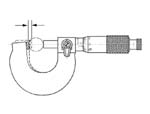
Whenever you use a handtool or precision gage, you should be aware of typical pitfalls that prevent good gage performance. These include measurement errors resulting from environmental conditions (dirt and temperature), loose and/or worn gage parts, and operator misuse. But there are other gaging pitfalls lying in wait that must be considered, both as part of good gage design and good measuring procedure. These issues become particularly important as the need for gage performance increases. They are typified by our three friends, Mr. Abbé, Mr. Hooke and Mr. Hertz, and they most likely sit with you while you are performing your gaging process. Let me introduce you.
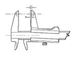
Meet Mr. Abbé, a noted optical designer. His principle states that maximum accuracy may be obtained when the reference scale and the workpiece being measured are aligned in the same measurement. This is the case when using a standard set of micrometers: The measuring scale (that is, the micrometer barrel or digital scale) is in line with the part and the reference contact. However, in the case of a caliper gage, this is not true. With this type of gage, the measuring scale is below the contacts, and if there is any angular movement to the jaws during measurement, Mr. Abbé says hello (See Figure 1).
Another type of gage where the measurement scale has often not been in line with the part is the horizontal length machine. Notice that on many of today's newly designed horizontal length measuring machines, great effort has been made to place the scale either in line or as close to the measuring line as possible.
Also, say hello to Mr. Hooke, a physicist who determined that the amount a spring stretches varies directly with the amount of force applied to it. Now, you may say "there are no springs in my micrometer," but the frame of the gage actually acts like a spring. Because springs are sometimes made of steel, steel gaging frames can act like springs. Whenever you turn the barrel of a micrometer down onto the part (Figure 2), you are applying force to the part and the reference contact. There is "spring" action taking place in the frame. This is one of the reasons, as noted previously, for the friction or ratchet drive used in the micrometer barrel. By employing a constant measuring force, the "spring" of the frame can be incorporated into the measurement and improve repeatability. This ratchet in the micrometer is a reminder that Mr. Hooke is still around.
Finally, we welcome Mr. Hertz, another physicist who developed a formula that determines the amount of surface deformation within a material's elastic limit (remember the springy steel) when two surfaces are pressed against each other under a certain force. There are formulas for cylindrical, spherical and planar surfaces. These formulas are important for determining the deformation of a workpiece caused by the measuring force. The results are typically small when working with steel, but they turn out to be important in gage block measurement. They also need to be considered when dealing with compressible materials.
For example, let's say we have a 0.125-inch radius diamond contact applying a gaging pressure of 6.4 ounces on a gage block. With a steel gage block, penetration would be approximately 10 microinches. However, with a carbide gage block, it would be about 6.6 microinches. That's pretty small—but in the gage block world, the difference can be a major portion of the block's tolerance. And if you know about it, you can deal with it.
In short, when all three of these guys get together and put their forces to work, it's party time! Understanding their principles and planning for their presence keeps them under control.


Related Content

Help Operators Understand Sizing Adjustments
Even when CNCs are equipped with automatic post-process gaging systems, there are always a few important adjustments that must be done manually. Don’t take operators understanding these adjustments for granted.
Read More
Ballbar Testing Benefits Low-Volume Manufacturing
Thanks to ballbar testing with a Renishaw QC20-W, the Autodesk Technology Centers now have more confidence in their machine tools.
Read More
The Link Between CNC Process Control and Powertrain Warranties
Ever since inventing the touch-trigger probe in 1972, Sir David McMurtry and his company Renishaw have been focused on achieving process control over its own manufacturing operations. That journey has had sweeping consequences for manufacturing at large.
Read More
The Many Ways of Measuring Thickness
While it may seem to be a straightforward check, there are many approaches to measuring thickness that are determined by the requirements of the part.
Read MoreRead Next

Building Out a Foundation for Student Machinists
Autodesk and Haas have teamed up to produce an introductory course for students that covers the basics of CAD, CAM and CNC while providing them with a portfolio part.
Read More
Setting Up the Building Blocks for a Digital Factory
Woodward Inc. spent over a year developing an API to connect machines to its digital factory. Caron Engineering’s MiConnect has cut most of this process while also granting the shop greater access to machine information.
Read More
Registration Now Open for the Precision Machining Technology Show (PMTS) 2025
The precision machining industry’s premier event returns to Cleveland, OH, April 1-3.
Read More