
Pushing Air Gaging Limits
Air gaging allows you to measure many jobs faster, more conveniently and more accurately than other gaging methods.

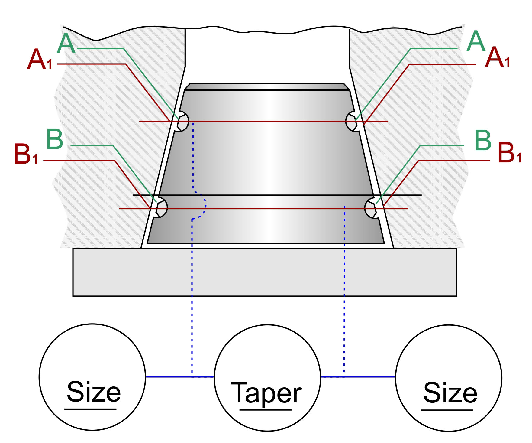
FIG 1. With the typical taper gage, the two pairs of jets are set to two different heights on the taper. The gage reflects a differential change between two diameters at a fixed distance along the part.

George Schuetz
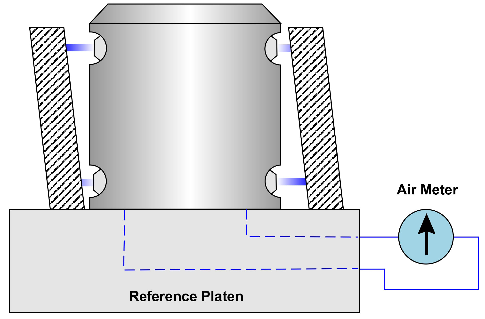
FIG 2. With a squareness (perpendicularity) gage, jet spacing is similar, but the circuit created to combine the jets is different. Top and bottom jets on each side of the air plug are channeled to opposite sides of a special air meter to provide a differential type measurement.
Share


Air gages also effectively measure all common types of dimensions and are particularly suited for checking dimensional relationships such as taper, parallelism, squareness, straightness and center distance. Match gaging, which permits the selection of mating parts with a specified amount of clearance or interference, is easily accomplished with just one reading on one dial.
One of the great things about air gaging is the fact that virtually no other gaging system can put the sensors (in this case the air jets) so close together to allow for multiple diameters or geometric conditions in very small pieces of tooling. However, the fact that you can get the sensors close together to make checks for taper or squareness may also impose limits, despite the measuring capability.
Let’s review some examples.
With the typical taper gage, whether it’s a “jam” style that measures only taper or a clearance style that measures two diameters and taper, the two pairs of jets are set to two different heights on the taper (see Figure 1). The gage reflects a differential change between two diameters at a fixed distance along the part.
With a squareness (perpendicularity) gage, jet spacing is similar, but the circuit created to combine the jets is different (see Figure 2). Top and bottom jets on each side of the air plug are channeled to opposite sides of a special air meter to provide a differential-type measurement. Lack of squareness is indicated by movement of the meter hand as the part is rotated on a reference platen. This method is used primarily when the squareness reading should not be influenced by any taper condition.
The limitations of these measurements stem from jet placement. With good machining, air jets can be put very close together. In fact, it is not unusual to see jets spaced as close as 0.20 inch between their center lines. But think about how this affects part tolerances.
Let’s say that the specified tolerance for taper is +0.001 inch/-0.000 inch per foot. This 0.001-inch per-foot tolerance seems easy enough to achieve until you look at the complexity of the inspection process. First, most parts we see are much shorter than 1 foot, so most air gages actually compare diameters that are just 3 or 4 inches apart. This is no problem. However, if you want to measure this taper tolerance over a very short distance, there can be issues.
For example, if we use the scenario above where we have 0.20-inch jet spacing, the part has to meet a gaged tolerance of 0.001 inch divided by 60, or 0.000016 inch. Most common air gaging resolves to 10 microinches, and even high-magnification air gaging safely resolves to only 5 microinches. This does not leave much room for any part, gage, environment, operator or master variation.
Now, think about the master for the gage. Masters are often at least five to ten times better then the system on which they are being used. Or, think about the gages required to measure these masters: There are enough zeros in these numbers to make the national debt envious!
Beyond that, there is the concept of trying to achieve a 10-percent gage repeatability and reproducibility (GR&R). As this is about 4 percent of part tolerance, or 0.64 microinch, it is just plain unattainable.
Perpendicularity gaging works in a similar way. It is often specified over the entire length of the surface being measured, and it is subject to ratio reduction like the angular reading seen in the taper check.
So, how does one achieve these measurements with certainty on the shop floor? With tighter tolerances, the old 10-to-1 rule for gaging is out the window. Achieving 5 to 1 may also be a stretch. At some point, some gaging may not be capable of these tight tolerances over such a short area. Is it gaging at this point or just an indication of what is happening? In some cases, an indication is all that can be expected.


Read Next

5 Rules of Thumb for Buying CNC Machine Tools
Use these tips to carefully plan your machine tool purchases and to avoid regretting your decision later.
Read More
Setting Up the Building Blocks for a Digital Factory
Woodward Inc. spent over a year developing an API to connect machines to its digital factory. Caron Engineering’s MiConnect has cut most of this process while also granting the shop greater access to machine information.
Read More
Building Out a Foundation for Student Machinists
Autodesk and Haas have teamed up to produce an introductory course for students that covers the basics of CAD, CAM and CNC while providing them with a portfolio part.
Read More