Share


For some shops, the flexibility of inserted carbide cutting tools might be too much of a good thing. “Carbide is safe and easy to use,” says Steven Howard, engineering and marketing manager for NTK Cutting Tools. The problem is that better-performing options can be easily overlooked—or worse, dismissed for the wrong reasons. “I’ve heard so many people say, ‘We tried ceramic cutting tools, but they didn’t work,’” he says. “Most of the time it was because they were making mistakes.”
Ceramic tools require more care than their carbide cousins, Mr. Howard explains. They operate according to fundamentally different principles. And yet, CAM programs written by newcomers to these tools often reveal no difference in approach to plotting tool motion or selecting parameters such as feeds, speeds and cutting depths. In these cases, results tend to be underwhelming.
Meanwhile, he says applications for ceramic insert cutters are expanding. Once relegated mostly to aerospace parts, heat-resistant alloys incorporating metals like nickel, cobalt and titanium are now increasingly common in automotive and energy industry applications. Such materials are ideal for ceramic. In one recent case, switching away from carbide on an oil-field pipe inlaid with Inconel 718 reduced an NTK customer’s cycle time from an hour and a half to less than four minutes. Ceramic is also useful for materials like hardened steel and cast iron.
In short, there is good reason for many manufacturers to consider (or to reconsider) ceramic cutting tools. However, if programmers continue to “think in carbide,” and to insist on blindly applying the same strategies they always have, ceramic tools are not likely to perform at their full potential. Based on a recent conversation with Mr. Howard, here are seven tips for those considering a trial or re-evaluation of ceramic tools:
Tip 1: Prioritize Surface Speed
“When you’re having problems, it’s human nature to slow down,” Mr. Howard says. “Like when you’re driving on a bad road—we all do it. But that’s a big mistake with ceramic tools.”
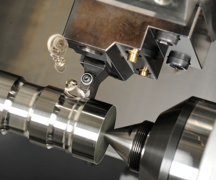
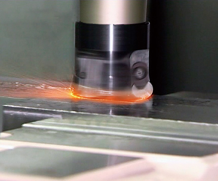
These cutters crave surface speed. More specifically, they crave heat. As opposed to the shearing action of carbide, ceramic melts the workpiece material ahead of it. Rather than generating chips that carry heat away, the goal is to generate intense pressure at the cutting zone, where temperatures can exceed 1,200ºF.
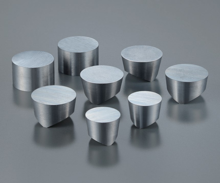
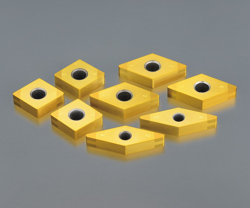
Lacking a binder material like the cobalt in carbide inserts, ceramic inserts are designed specifically to withstand this heat-generating pressure. Inserts are generally thick, and chip breakers are mostly nonexistent. Large, rounded corner radii are the preferred choice if the application allows it. “We’re generally trying to drive the forces into the middle of the insert,” Mr. Howard says.
Running 8 to 10 times as fast as a carbide tool may be frightening—particularly when the cutting zone spits red- or even white-hot chips—but maintaining speed is critical. Fail to maintain adequate surface feet per minute (sfm), or cautiously ramp up to speed, and the cut becomes mechanical. Cutting speed and tool life suffer.
Tip 2: Maintain Contact
Interrupted cuts are bad for ceramics because disengaging from the workpiece allows the tool to cool. When interruptions can’t be avoided, programmers should power through rather than approaching with caution, as they likely would with carbide. In fact, programmers should strive to maintain tool contact with the workpiece for as much of the operation as possible, particularly when milling.
Tip 3: Feed Fast
High spindle speed is an obvious requirement to ensure sufficient sfm. Aggressive feed rates are also desirable, although for a different, possibly counterintuitive reason: preventing tool wear. “The fewer rotations an insert completes, the longer it’s going to last. You don’t want to back off to try and protect it,” Mr. Howard says. If the feed rate must be reduced for other reasons, such as a sharp corner, programmers should strive to keep spindle speed (and thus, sfm) as high as possible.
Tip 4: Take Care in Corners
Ceramic’s hardness and resulting heat tolerance comes with a price: brittleness. Even with a robust insert, a general rule is to reduce feed rates by half in corners. This strategy can protect against extra pressure when a larger portion of the insert engages the material.
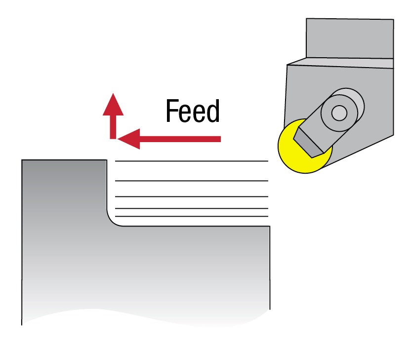
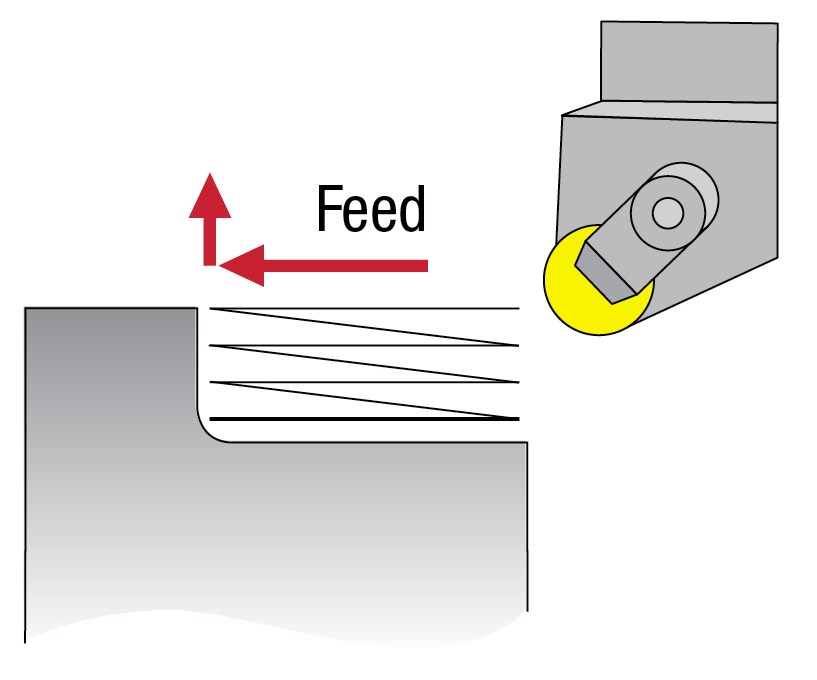
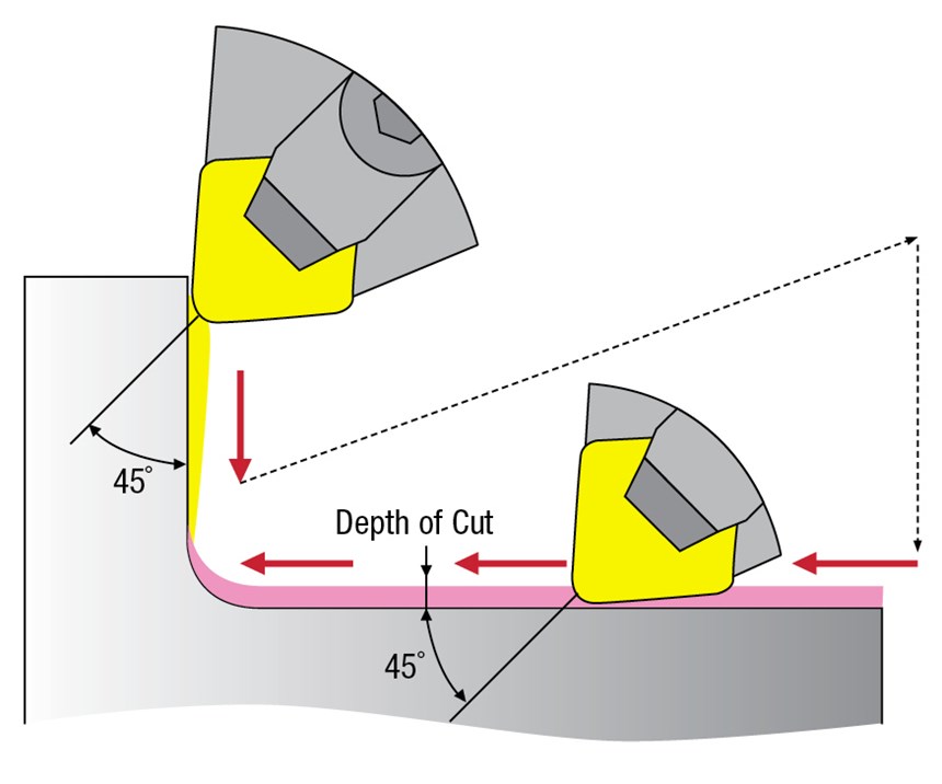
Sharper corners and diamond-shaped insert points require special care. Whereas a tool path developed for carbide might simply drive the insert around a 90-degree turned corner, engaging a ceramic cutter to this extent is likely to break it, Mr. Howard says. Rather, the preferred approach (illustrated in the picture gallery above) is to first cut along one wall, pull away, then engage the other wall and feed in the opposite direction (in this case, removing the tool from the material and allowing it to cool slightly is preferable to subjecting it to forces that may break it). The cut should remain below the 45-degree mark on the cutter radius to minimize notching and facilitate feeding in two directions.
Tip 5: Round Sharp Edges
Even when corners and other geometry dictate a thinner, more brittle insert, NTK often recommends a slight T-land or honed edge. Particularly with heat-resistant alloys, such features can reduce notching, flaking and built-up edge.
This advice goes for more than just inserts. Programmers should also take care to round off areas where the cutter will enter or exit the workpiece before machining begins. Otherwise, the insert might chip or break.
Tip 6: Turn Shallow
Given the prevalence of large, rounded nose radii, machinists might be tempted to cut too deep with this relatively brittle material. “They’ll break the insert and then say, ‘ceramic doesn’t work,’ but they’ve actually overtaxed it,” Mr. Howard says.
Such scenarios are particularly common in turning operations. A round insert can leverage chip thinning, a phenomenon that reduces cutting pressure and is more common to milling with triangle- or diamond-shaped inserts. “With a round insert, the less your depth of cut, the more benefits you get from chip thinning,” Mr. Howard explains. “When you exceed a certain depth of cut, the front of the insert is no longer thinning. It is taking the full brunt of the full feed.”
Tip 7: Vary Cutting Depths
Recommendations for other insert shapes differ. For instance, a deeper cut may be advised for rough turning with a triangle or diamond insert. Whatever the specifics of the application, programmers should make sure to vary the cutting depth with each pass. The resulting change in the location of wear on the insert reduces the chance of notching and premature tool failure. Ramping cuts in the same direction provide the same effect.
The Work is Worthwhile
The list above is by no means comprehensive. However, it illustrates the extent to which programmers comfortable with carbide need to think differently about how they use ceramic tools. And thinking differently is likely to lead programmers to rely less on automated CAM software functions developed with carbide tools in mind.
Not all examples are as simple as adding a chamfer or ensuring the correct approach to a corner. Consider a part that requires milling tower-like structures from the bottom of a cavity. With a modern CAM system, programming a routine to mill out the cavity around these structures is a simple matter. However, the resulting tool path is likely to work better with a carbide tool than a ceramic one. “It would probably start carving away material in passes like a snow shovel, but ceramic wants to act more like a snowblower—you never want a snowblower to not have snow in it,” Mr. Howard explains, referencing the need to maintain heat by keeping the cutter engaged. In an application like this, he says, “You might have to go through and plan every cutter path.”
Nonetheless, any extra thought and care can be well worth it. As an example, he cites an aerospace manufacturer that had become frustrated by the lack of improvement in work involving milled structures just like those in the previous example. “We went in and tweaked their program, and ceramics went from being uneconomical to doubling the amount of parts they could make,” Mr. Howard says. “After that, their customer sent them twice as much work.”
Related Content
Custom PCD Tools Extend Shop’s Tool Life Upward of Ten Times
Adopting PCD tooling has extended FT Precision’s tool life from days to months — and the test drill is still going strong.
Read MoreThe Impact of Cutting Teeth Spacing on Machining Stability
Many cutter designs are available, and variable teeth spacing (or variable pitch) cutters can be used to influence milling stability. Let’s discuss why teeth spacing affects stability.
Read MoreForm Tapping Improves Tool Life, Costs
Moving from cut tapping to form tapping for a notable application cut tooling costs at Siemens Energy and increased tool life a hundredfold.
Read MoreShoulder Milling Cuts Racing Part's Cycle Time By Over 50%
Pairing a shoulder mill with a five-axis machine has cut costs and cycle times for one of TTI Machine’s parts, enabling it to support a niche racing community.
Read MoreRead Next
Building Out a Foundation for Student Machinists
Autodesk and Haas have teamed up to produce an introductory course for students that covers the basics of CAD, CAM and CNC while providing them with a portfolio part.
Read MoreRegistration Now Open for the Precision Machining Technology Show (PMTS) 2025
The precision machining industry’s premier event returns to Cleveland, OH, April 1-3.
Read More5 Rules of Thumb for Buying CNC Machine Tools
Use these tips to carefully plan your machine tool purchases and to avoid regretting your decision later.
Read More




.jpg;maxWidth=300;quality=90)


.jpg;maxWidth=300;quality=90)

