Widening Interest In Twist Drills
Wide-web drills with high-performance points help speed machining center paybacks.
Share


Takumi USA
Featured Content
View More


Hwacheon Machinery America, Inc.
Featured Content
View More.png;maxWidth=45)
DMG MORI - Cincinnati
Featured Content
View More

There was a time when many metalworking manufacturers felt "a drill is a drill is a drill." But modern machine tools, and especially today's advanced machining centers, have changed that belief.
Today, the focus is on how to maximize utilization of machining centers in order to speed paybacks on these higher technology machine tools, which also carry higher price tags.
Since 50 to 70 percent of all production time is used to make holes, it's apparent that any improvements made to the drilling process—including the choice of the right drill, drill point geometry and sharpening methods—will make manufacturing more productive and improve quality. So it is not surprising that companies looking to earn higher return on their machine tool investments also are looking at the basic twist drill with renewed interest and depth of investigation.
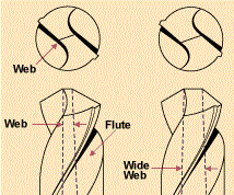
One result of this deeper investigation is more frequent application of wide-web drills. The web of a twist drill is the core section of the drill body, which connects the two outer fluted sections (see Figure 1). The web thickness comprises 10 to 20 percent of a standard drill's diameter (see Figure 2). On a wide-web drill, web thickness increases to about 33 to 40 percent of the drill diameter.
Because wider web drills are more rigid than standard drills, they always have been able to drill straighter, deeper, more accurate hole diameters. In addition, wide-web drills typically permit about 20 percent higher feed rates, and the strength of a wide web makes the tool ideal for deep cuts in hard material. By comparison, long drills with standard webs have less torsional rigidity, and thus tend to "unwind" and chatter if hard material is being drilled, in deep-hole drilling applications or as the drill becomes dull.
Despite the acknowledged advantages of wide-web drills, their earlier acceptance was slowed by a costly disadvantage. As web thickness increases, the thrust forces required for drill penetration also increase. Therefore, successful use of wide-web drills demanded a method to reduce web thickness at the point. A common method of web thinning involved hand positioning of the drill at a pedestal grinder—both inaccurate and non-repeatable.
Through what might be termed an "evolutionary" pace of development, however, wide-web drills now are gaining stronger acceptance. A review of this evolution, starting with some fundamentals of twist drill geometry, helps to explain the different reasons why more wide-web drills are being used to help speed paybacks on machining centers today.
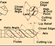
Figure 3 is a diagram with the nomenclature of a basic twist drill. Like any other cutting tool in metalworking, the twist drill works around the principle of chip formation.
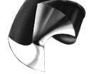
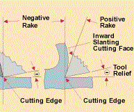
Chip formation is controlled largely by the rake angle of the cutting tool. Rake can be defined as the angle of the cutting face relative to the tool's axis. When the cutting face slants ahead of the cutting edge, this is negative rake. Any time the cutting edge is ahead of the cutting face, this is positive rake (see Figure 4).
A positive rake tool is able to cut or shear off the material. An analogy of positive rake is an apple peeler that cleanly cuts the fruit's skin in a continuous chip. This cutting action requires little physical effort.
The negative rake tool does not shear material, but rather pushes the material ahead of it. An analogy of negative rake is a bulldozer that scrapes the surface. The material bunches up in front of the blade as it is pushed away. This cutting action is a direct result of brute force.
Figure 1 shows that a drill's end comprises two distinctly different cutting areas—the cutting lips and the chisel edge.
The cutting lips have a positive rake cutting angle, which is determined by the flute's helix angle or twist of the drill. Cutting speed is determined by the speed of the drill's revolution, and chip thickness is determined by the feed rate. This area of the drill is fairly straight-forward, and simply follows conventional chip-making theory.
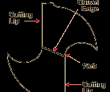
The second area is the chisel. This is the edge of the drill's end across the web that connects the cutting lips. This small area is what creates most of the problems in drilling and is typically the most ignored feature of a drill.
Drill Point Geometry's Critical Role
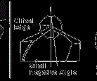
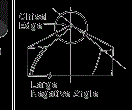
Whether or not the chisel edge can form a chip depends upon the amount of rake. With a small negative rake—up to 10 degrees for example—a chip still can be formed. However, when the rake gets as high as 45 degrees, there is no ability for chip formation.
On a conventional point, the chisel edge has a large negative-rake cutting angle, which is determined by the point angle (see Figure 5). The extremely negative rake at the chisel edge does not allow chip formation—only extrusion or pushing o
Because the chisel of a conventional drill point has a blunt negative cutting edge, it relies on force to remove the material. For a ½-inch drill of standard web width and conventional point geometry, more than 50 percent of the force that is required for drilling is created by the chisel.
The length of a chisel edge is determined by web thickness at the point. On wide-web drills, the chisel creates 70 to 75 percent of the force required for drill penetration. Therefore, grinding methods to reduce penetration forces became imperative.
As with any drill using a conventionally ground drill point, decreasing the web thickness on a wide-web drill is done by either splitting or thinning (notching) the point (see Figure 6). Both of these secondary grinding operations remove metal from the conventional drill point in order to decrease web thickness at the chisel edge and reduce the feed pressure required for penetration.
In addition to requiring a secondary operation, splitting or thinning the point of any drill—including those with heavy webs—also involves special grinding skills, and often requires a dedicated machine for splitting or web thinning.
Secondary grinding operations must be performed accurately to ensure that the drill point is symmetrical. Lack of symmetry in the lengths or angles of a twist drill's cutting lips can create cutting forces which are unbalanced, because one cutting edge is doing more work than the other. When this happens, centering action of the tool is poor, and the finished hole is not round, straight or correctly aligned. In addition to oversized holes, tool wear is more rapid.
As a result of the multiple grinding operations and their related tool handling, metalworking manufacturers have experienced problems with consistency of holes drilled by points which have been thinned or split.
Despite such drawbacks, wide-web drills continued to receive slowly increasing acceptance because of their advantages identified earlier. At the same time, manufacturers continued their search for a way to eliminate the high costs of secondary grinding operations and the less-than-satisfactory drill performance which has resulted.
In the past, such a quest had not been important to most manufacturers because the total machining process included enough other limitations on accuracy that a better drill alone couldn't make an appreciable difference in hole-making quality anyway. With the advent of higher performing CNC machines becoming affordable in every shop, however, the benefits of companion high-performance drill points can be realized, and have justified further drill point development.
High-Performance Drill Points Relieve The Pressure
While the search to "make a good drill better" led tool engineers to explore many new designs, it also included reviews of point geometries already proven on drills with standard web thickness. Among these were two drill points—Winslow-Helical and Bickford—which had proven to be consistently high performers on standard drills but had little performance record on wide-web drills.
In the early 1960s, Jim Winslow had developed the helical drill point geometry shown in Figure 7. This point produces higher quality holes than conventional points can, and with higher feed rates as well as lower thrust.
The helical point's ability to use higher feed rates introduces significant advantages for both hole-making productivity and quality. Using a heavier feed gives a drill better centering action and also helps to create a thicker chip. The latter occurs because the heavier feed enables a tool to cut metal the way it was designed to perform, rather than just "rub" on a thin chip.
When a thicker chip is made, more heat goes into the chip and less heat into the drill. This can be observed when chip color becomes more blue while tool cutting edges show less evidence of heat. Heat dissipated into the thicker chip produces better chip flow because the chip curls more and breaks up better.
Among other advantages, improved chip flow avoids the long metal ribbons which can cause "birdnesting" problems. It also tends to eliminate the need for peck drilling, or backing out to clear chips and then drilling deeper. In addition, better chip flow increases the coolant flow and enhances drill life.
The Winslow-Helical point differs from conventional drill points in that it has a slightly extended chisel, which creates an active cutting edge ahead of each side of the chisel. This clearance eliminates the limitations involved with conventional point geometry.
The continuous cutting edge created by the prominent "S"-shaped chisel of the Winslow-Helical point starts at the center of the drill and blends in with the cutting lip. Because the helical point cuts along the entire length of this cutting edge, cutting forces are distributed more evenly, so chip formation and chip flow are greatly improved.
On a Winslow-Helical point, the crown of the web section creates a single point of contact between the drill and the workpiece. As a result, the tool is self-centering. In many CNC applications, center drilling is eliminated when using a drill with a Winslow-Helical point.
The combination of single-point contact that starts the drill on center by itself, plus a balanced cutting force across the chisel enables a drill to start making a chip immediately and to continue that chip formation with less force required throughout the process. This capability produces straighter, rounder holes.
Secondary reaming and spot drilling operations also can be eliminated in many cases, because the point cuts so close to the diameter of the drill.
The progress achieved with the Winslow-Helical drill point has been taken a step further with the Bickford Point (see Figure 8).
The Bickford point has the same self-centering, free-cutting characteristics of the Winslow-Helical point and adds a blended, rounded edge or radiused corner. This further increases tool life and also minimizes burr formation at the moment of breakthrough.
(The Bickford point should not be used in any hand-held drilling operations because it does tend to grab the workpiece during breakthrough.)
Compared with the straight chisel geometry of a conventional drill point, the crowned S-shaped chisel of both the Winslow-Helical and Bickford points requires less thrust and generates less heat. The heat that is produced dissipates more efficiently. Doubled feed rates and longer tool life are common benefits.
The chisel cutting action of higher performing drill points became even more important when parabolic-style drills were developed in the early 1980s. These heavy-web drills offer higher rigidity and increased flute area for chip removal on deep-hole drilling operations. Although the original parabolic-style drills were developed for cutting efficiency, they still included the split-point technology.
Today, more companies are putting the inherent advantages of parabolic drills to work by adding high-performance point geometries. At the same time, they are avoiding the costs of wide-web secondary grinding operations.
The following four examples illustrate that the performance differences discussed here are not mere "textbook theory." In each case, the advantages were gained by switching from conventional drills to wide-web drills that incorporate either Winslow-Helical or Bickford point geometries (see Figure 9).
- A Midwest casting manufacturer previously limited by a tool life of fewer than two 1-inch-diameter holes while drilling through 8-inch-thick chromium copper at 0.007 ipr and 486 rpm now makes 24 holes of the same size in the same material at the same feed and speed rates before changing drills.
- An East Coast aerospace manufacturer who formerly had to replace a ½-inch-diameter HSS-cobalt 135-degree split-point drill after every five to ten stainless steel parts because of excessive burr formation now drills 30 to 40 of the same parts before changing tools; the manufacturer also has eliminated three reaming operations needed before.
- Head-to-head tool tests conducted by a major agricultural equipment manufacturer who was averaging 100 holes on cast-steel wheels per each standard 21/32-inch drill showed that, when a higher performing drill was used, the company was able to produce 1,570 holes, and had to remove only 0.014 to 0.020 inch of stock when resharpening.
- Another Midwest manufacturer switched from conventional drill points for a series of 21/32-inch, 17/32-inch and 27/64-inch-diameter holes in cast AISI 1020 steel. This manufacturer increased both feed and speed rates by 20 percent, saved nearly 13 1/2 hours of drilling time on the same workpiece and eliminated a separate center-drilling sequence.
Looking at today's high-performance drills as a group, all of them incorporate some type of design to allow chip formation across the entire web. The resulting upgrades in drilling efficiency and hole quality have proved significant in helping to realize faster paybacks from advanced-technology machining centers.
About the author: Paul T. Schroeder is a supervisor for tooling systems at Giddings & Lewis Machine Tools (Fond du Lac, W
Read Next
Registration Now Open for the Precision Machining Technology Show (PMTS) 2025
The precision machining industry’s premier event returns to Cleveland, OH, April 1-3.
Read More5 Rules of Thumb for Buying CNC Machine Tools
Use these tips to carefully plan your machine tool purchases and to avoid regretting your decision later.
Read MoreBuilding Out a Foundation for Student Machinists
Autodesk and Haas have teamed up to produce an introductory course for students that covers the basics of CAD, CAM and CNC while providing them with a portfolio part.
Read More


.png;maxWidth=150)


