When Spindle Speed is a Constraint
Though it won’t replace high speed machining, Boeing sees “low speed machining” as a viable supplement to higher-rpm machines. Using new tools and techniques, a shop’s lower-rpm machining centers can realize much more of their potential productivity in milling aluminum aircraft parts.
Share


The phrase “high speed machining” emphasizes the word “speed,” but running at a high spindle speed has never been the primary goal. High speed machining aims instead just to leverage spindle speed—realizing a high metal removal rate within a single milling cycle that brings the raw workpiece as close to being a completed part as possible. The completed part and the high metal removal rate are the two goals. Speed is only the means—and speed is not even the only means for bringing these two goals together.
Over the past several years, refinements in cutting tool technology have enabled shops to achieve high metal removal rates at lower spindle speeds as well. As a result, a Boeing team in St. Louis, Missouri that teaches high speed machining techniques to Boeing suppliers now also teaches lower-rpm techniques—often for shops that are lacking in high speed capacity. For Boeing, this newer set of techniques goes by the deceptively humble label of “low speed machining,” a term that actually entails a high level of productivity.
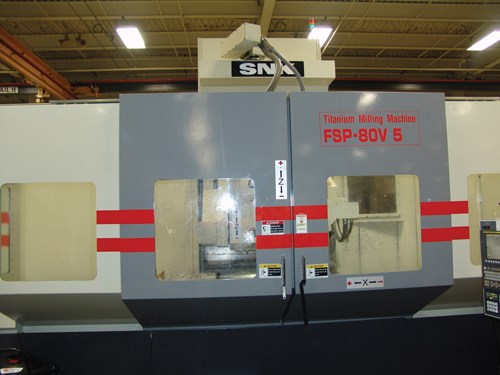
One part in particular illustrates this. The aluminum part in the photo to the right had been produced through high speed machining on a large machining center at Boeing—a machine capable of 24,000 rpm. But that machine was over-scheduled, creating pressure to make the part some other way. A machining center capable of 4,000 rpm happened to be available.
The Boeing team developed a process for making maximum use of the capabilities of this lower-speed machine, so that this machine alone could produce the part efficiently. In doing so, the team also refined an approach to low speed machining that it has since helped various suppliers adopt. The process involves roughing with high feed mills, as well as with solid carbide end mills capable of heavy depths of cut and chip loads. The process also involves finishing features rapidly using high-flute-count end mills.
Run time for the part had been 61 minutes. This was the real time for the high speed machining cycle, with tool changes and acceleration/deceleration included.
For the same part in the new low speed process, the run time was nearly the same—67 minutes.
Boeing engineer Eric Stern is a member of the St. Louis machining team, which is part of the company’s Research and Technology Group. He stresses that high speed machining is still preferable. Typically HSM will be more productive, often markedly so. Even the high speed cycle above probably would have clocked better than 61 minutes if its programming and other aspects of the process had received as much analysis as the low speed process ultimately did. However, this time served as the accepted benchmark—and the productivity of low speed machining came respectably close.
For many suppliers, this is significant. Many don’t have a high-rpm machining center, let alone enough of the kind of work that could justify one. Many others face overscheduling of high speed machines, while lower-speed machines in the shop remain available. By helping shops increase productivity at all speed levels, the Boeing team hopes to expand capacity throughout the company’s supply chain.
Here are some tips the team offers for realizing more productive low speed machining:
Go Back To Roughing
Roughing and finishing are distinctions that can become unnecessary in high speed machining of aircraft components, because machining is done through precise heavy cuts that both hog out material and achieve the final dimensions. However, low speed machining requires a return to roughing and finishing, Boeing says. That’s because roughing is likely to entail high-horsepower cuts that aren’t appropriate for achieving the final dimensional tolerances of the part’s features.
In roughing, the key is to make as much use as possible of the machine’s available horsepower. On a machine where high spindle speed is not available, this horsepower provides the alternate means to high productivity.
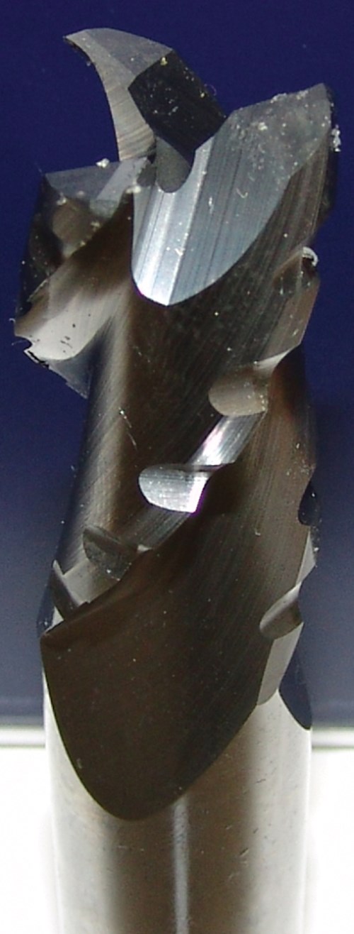
Making the most of the horsepower might involve experimenting with different choices in tools. On the part mentioned previously, the Boeing team initially applied a standard roughing end mill for aluminum. The tool permitted a maximum metal removal rate of 6.3 cubic inches per minute, taking advantage of only 2 hp. By contrast, a different tool, the SwiftCarb rougher shown on this page, enabled the machine to employ 14.5 hp in this cut—partly because of the chip clearance provided by the shredding effect of the flute design. The corresponding metal removal rate with this tool was 45 cubic inches per minute.
Use Flutes For Finishing
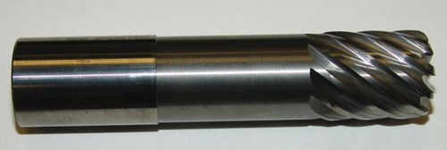
For finishing, the best tool choice is different. An end mill with a large number of flutes can achieve a productive inch-per-minute feed rate at low spindle speeds. The 10-flute milling tool shown on the facing page is a standard tool Boeing recommends for finishing applications in titanium. The tool works efficiently for finishing passes in aluminum as well. In fact, in aluminum, the 1-inch diameter tool can be run at a radial immersion of 0.3 inch with an axial depth of cut of 1 inch—parameters that wouldn’t be considered in
titanium.
The caveat with this tool (and with low speed machining of aircraft components in general) is that the internal corners of the part have to be machined first. Numerous internal corners are typical of aircraft structural members, which often consist of many pockets. For a finishing tool milling with a light radial depth of cut, the radial engagement dramatically increases when the tool enters a corner. Therefore, for the protection of both tool and workpiece, the material needs to be machined out of the corners (using some different type of tool) before these fast finishing passes are run.
Other Roughing Tools
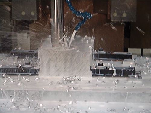
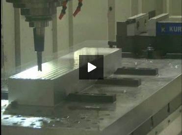
Other types of tools are also likely to be valuable. Chief among these are high feed mills, Boeing says. The last photo above—a still from Boeing video footage under "Editor Picks" at right—shows a high feed milling tool from Iscar. “High feed” tools use a cutting edge geometry that takes advantage of axial chip thinning to achieve a higher feed rate than a comparable tool with a more standard geometry would be able to realize. When roughing volumes are large enough to permit this type of tool, Mr. Stern says the high feed mill can be a reliable way to achieve 50 to 60 cubic inches per minute, even when the spindle speed is low.
One final tool that also deserves consideration is a plunge roughing mill. Few shops would consider such a tool for aluminum. Most instead see plunge roughing as a technique for hard metals. However, when low spindle speed is a process constraint, plunge roughing might be the most productive approach, even in the soft material. The choice comes down to the shape of the pocket—specifically how much material plunging would leave behind in need of follow-up machining. Plunge roughing would likely make no sense if high spindle speed was available, Boeing says. However, given a low speed machine, this technique might be an element of the process that realizes the highest productivity.
Related Content
How to Accelerate Robotic Deburring & Automated Material Removal
Pairing automation with air-driven motors that push cutting tool speeds up to 65,000 RPM with no duty cycle can dramatically improve throughput and improve finishing.
Read MoreRead Next
Video: High Feed Milling in Aluminum
Footage shows roughing at 48 cubic inch per minute on a standard-speed machining center.
Read MoreVideo: Plunge Roughing in Aluminum
Even in aluminum, plunge roughing can be an effective way to realize high productivity.
Read MoreBuilding Out a Foundation for Student Machinists
Autodesk and Haas have teamed up to produce an introductory course for students that covers the basics of CAD, CAM and CNC while providing them with a portfolio part.
Read More

