
Tool Path Strategies For High Speed Machining
CAD/CAM features can be key to realizing effective High Speed Machining.
Share


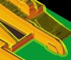
Here is an example of follow-up remachining tool paths based on knowledge of stock remaining. These tool paths show steep areas machined by Z-level machining, and shallow areas machined using a spiral racetrack pattern.
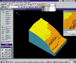
Smart machining varies down-step distances between Z levels to achieve near-net-shape rough machining. Functionality like this may make it possible to eliminate the semi-finish pass
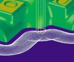
Plunge-roughing tool paths resemble drilling moves. This technique is particularly effective at roughing out deep cavities.
Sharp direction changes can cause a CNC with look-ahead to slow down. To machine internal corners more effectively in HSM, tool paths use rounded moves to change direction.
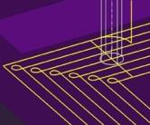
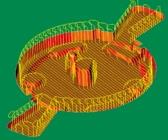
Here is an example of a trochoid milling tool path. The always-curving path permits the machine to maintain a more constant feed rate.
When the feed rate gets high enough, simple loops between adjacent tool paths may still be too sharp. The “golf club” stepover can let the process realize and maintain a higher overall feed rate.
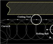
A trochoid is any curve that is the locus of a point fixed to a curve A, while A rolls on another curve B without slipping.
There are many components to an effective high speed machining process for mold and die makers. Much has been written about the impact HSM has had on CNC machine tools, spindles, toolholders, cutting tools, and controls. Often forgotten is high speed machining’s impact on tool path programming techniques.
CAD/CAM technology is evolving today to meet the specific needs for new tool path strategies to suit the HSM environment. Here, HSM can be defined as the use of higher spindle speeds and feed rates to remove material faster without a degradation of part quality. The goal is to finish mill molds and dies to net shape, to improve surface finish and geometric accuracy so that polishing can be reduced or eliminated.


To facilitate high speed machining, a CAM system should:
- Maintain a constant chip load
- Minimize feed rate losses
- Maximize program processing speed
The challenge to the CAD/CAM system is to make passes with very small stepovers at very high feed rates. And this must be accomplished without forcing the tool to make sharp turns, because the look-ahead features of HSM controls will automatically reduce the feed rate when they detect a corner approaching. In addition, in order to overcome data starvation—which will also impair the feed rate—the CAD/CAM system may be required to output tool paths appropriate to HSM controls capable of running NURBS-based G-code.
This article discusses CAD/CAM features that can help die/mold shops realize effective HSM.
Smart Machining
“Smart machining” is a feature that aims to produce an intelligent, optimized tool path. Its functionality can include options for examining data between Z layers—including HSM feed connections, slope control machining, and geometry identification.
To achieve near net shape when roughing, it is important for the CAM software to understand what changes in surface topology occur between the layers of down-steps. Knowledge of stock remaining (KSR) algorithms must look ahead to determine where extra down-steps are necessary. Smart machining is how a CAM system machines this “between layers” material. By roughing in this manner, often the semi-finish pass may be eliminated, saving on machine time and tool wear.
Smart machining may also include helical ramping functionality. This is used for pocket machining. The helical ramping function determines helical movement based on entry angle and geometry. This function is most important when the tool reaches a closed area of workpiece. It can make the cut shorter and safer by eliminating air cutting, as a result of tailoring the tool path to the geometry of the enclosed feature.
Knowledge Of Stock Remaining
Lately, many leading-edge CAD/CAM systems have introduced “re-roughing.” The re-roughing idea is at the heart of knowledge-of-stock remaining functionality.
The technique is excellent for shops where different roughing methods are employed. It works like this: Initial rough machining is performed first, then the resulting form is used as the new stock for a subsequent roughing tool path. Roughing can then proceed according to a different method—parallel, spiral, stock-spiral, what have you—with just the new stock. A likely result is a more efficient overall cutting strategy that keeps the tool in the material to reduce air cutting.
Similarly, knowledge of stock remaining allows tool paths to be created in areas where previous tools did not remove all of the material. There are many methods to remove this uncut material, including pencil tracing and rest milling.
The tool path trajectory for these follow-up machining strategies is optimized based on the knowledge of stock remaining from the previous tool path. For example, the tool trajectory is optimized to protect the tool and the holder from gouging based on the remaining stock.
The follow-up functions make the finish machining process more effective. Without pencil tracing, rest milling, and similar re-machining strategies, the finishing tool could be fed into a considerably larger volume of material (where it would probably break) when it reached the corners of enclosed areas. Re-machining relieves these corners.
Cornering
How to include corners in the overall tool paths is also an important consideration. In order to produce optimized tool paths for HSM, the CAD/CAM system must be able to deal effectively with internal sharp corners in the workpiece. A corner treatment function for HSM rounds the sharp motion out of the tool path. If allowed to remain, this sharp motion would be seen by the controller’s look-ahead function, which would reduce the feed rate accordingly. A CAM system that can generate fluid tool motions during corner machining can maintain more consistent high feed rates.
Side Steps
Side steps are the connections that create effective transitions between adjacent tool paths when feed rates are particularly high. Parallel scan-line surface machining is the type of machining that has been used for the last ten years to finish machine multi-surface models. This type of machining tends to produce sharp stepover moves at the end of every pass. Using simple “looping” tool paths in place of sharper turns between scan passes is an appropriate solution at moderate feed rates (20-40 ipm). However, at higher feeds, these simple rounded moves are still too sharp. An alternative that has proven more effective in some cases is a “golf club” stepover between passes.
NURBS-Based Tool Paths
The new G-code “G6.2” represents the NURBS spline. This command expands the choices from traditional linear and circular interpolation to interpolation along a spline represented by control points and knot points. By consolidating a complex, curving tool path into a single line of the program, this function saves on NC data, potentially resulting in more fluid high speed machining.
Some CAD/CAM systems—but not all—create the tool path directly in the spline format. The resulting tool path incorporates direct knowledge of the CAD model. This is important because some CAM systems generate NURBS tool paths based instead on the linear tool path, by approximating this linear path in terms of NURBS paths. Because this is a double approximation, tolerance stacking errors may result.
Trochoidal Machining
One of the newer techniques to increase rough machining speed involves a tool path strategy called trochoidal machining. This machining style removes material using the side knife-edge of the cutting tool.
“ Trochoid” describes a type of curve. A trochoid is the trace of a point fixed on a circle that rolls along a line. More generally, a trochoid is any curve that is the locus of a point fixed to a curve A, while A rolls on another curve B without slipping. (See illustration, below.)
Trochoidal machining is well suited to HSM because the cutting tool always moves along a curve of constant radius. This allows a consistent feed rate to be maintained throughout the machining process.
Plunge Roughing
A style of roughing called plunge roughing uses specially made cutting tools to machine deep molds and dies. Plunge roughing employs a drill-type tool path to remove material from deep within the cavity in the Z direction of the machining center. The result has proven to be an efficient method of roughing deep-cavity geometry.
Plunge roughing is drawing attention in machining large molds and dies. An extended protrusion in the tool is required for machining these workpieces. In typical milling, this extended protrusion would lead to vibration. But in this Z-directed machining, vibration is reduced, opening the door to more efficient roughing in many processes.
Plunge-roughing tool paths resemble drilling moves. This technique is particularly effective at roughing out deep cavities.
The Next Step
The use of HSM strategies normally requires the material to be removed with very shallow cuts and with small stepover. The smoothness of the machined surface is determined in large part by the height of the scallop between adjacent passes . . . and by taking a smaller and smarter stepover, the scallop height goes down. Thus, lighter depth of cuts contribute to reduced hand polishing. At the same time, HSM offers an efficient way to use very small tools. This can make it practical for high-speed CNC machines to generate fine details that might otherwise require inserts or EDM. Reducing or eliminating EDM can lead to substantial time-savings—not only because EDM is a slow process, but also because it requires the additional step of producing the electrode.
In other words, high speed machining lets the machining center do more. That’s why the complement to high speed machining, in the minds of many CAD/CAM developers, is a system that can automate much of a machining center’s programming.
The ultimate aim is to have a CAM system that can recognize features and automatically machine the workpiece using the shop’s best practices. The next generation of CAD/CAM systems will marry both manufacturing feature recognition and knowledge-based machining strategies to automate the complete mold machining process. The resulting system will provide complete automation “out of the box,” and yet still allow experienced toolmakers to tailor the system to match their shop practices. When will this system arrive? As an industry, we’ll get there one small step—or stepover—at a time.
About the author: Dan Marinac is strategic marketing manager for Cimatron Ltd. (Livonia, Michigan).


Related Content

How to Accelerate Robotic Deburring & Automated Material Removal
Pairing automation with air-driven motors that push cutting tool speeds up to 65,000 RPM with no duty cycle can dramatically improve throughput and improve finishing.
Read MoreRead Next

Building Out a Foundation for Student Machinists
Autodesk and Haas have teamed up to produce an introductory course for students that covers the basics of CAD, CAM and CNC while providing them with a portfolio part.
Read More
5 Rules of Thumb for Buying CNC Machine Tools
Use these tips to carefully plan your machine tool purchases and to avoid regretting your decision later.
Read More
Registration Now Open for the Precision Machining Technology Show (PMTS) 2025
The precision machining industry’s premier event returns to Cleveland, OH, April 1-3.
Read More