The Case For Optimized Inserts
A carbide insert is an engineered system consisting of substrate, coating, geometry and other components designed to work together. Insert manufacturers are getting very adept at optimizing this system and matching it to a given application.
Users of carbide inserts often fall into two distinct camps. On one side, there are those shops that are looking for a "universal" insert grade that will effectively handle a wide variety of applications, even if it means tolerating less than maximum metal removal rates in certain cases. The advantages are reduced tooling inventory, standardized programming routines, simplified setup procedures, among other sought-after benefits. Unfortunately, this universal insert grade is an elusive goal for cutting tool manufacturers, although considerable R&D efforts are still being devoted to this quest.
On the other side, there are those shops that strive to find the perfect match between the insert and the application, a match-up that will give them the highest possible metal removal rates, best surface finish, longest tool life, and so on. Maximum productivity and optimal results are what they're after. However, identifying that "perfect" insert hasn't always been easy or certain—the proliferation of insert grades and styles can be bewildering. And even if a shop can find the ideal solution, it has to maintain the machining conditions that allow the near-perfect insert to deliver its full potential, but shops haven't always had reliable information on what those conditions are.
As a matter of fact, most shops are caught somewhere in the middle of these two camps, being pulled in both directions at once.
But if you look at recent developments emerging from cutting tool manufacturers, the trend is decidedly toward the optimized insert. With today's understanding of the sophisticated factors and forces at work in a successful application, it is apparent that certain vendors are able to deliver an extremely productive solution for a very specific set of machining conditions. And they should be able to provide highly reliable information about using these tools to get the intended results.
Knowing something about the complex interactions of the critical components that unite to produce an optimized cutting system will help you understand why this systematized approach can be so effective. It will also help explain how vendors can guide you to the best insert with more confidence and certainty than ever before. Let's review some of the systems elements that an insert manufacturer has to work with and then look at how these elements can be engineered in combination to suit an application. In light of this discussion, you might find yourself reconsidering your approach to insert selection.
The Elements
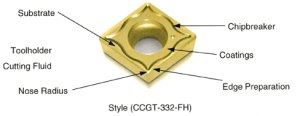
Every successful cutting tool application represents a combination of:
- a substrate,
- one or more coatings in most, but not all, cases,
- a chipbreaker, or "top form" geometry,
- a specific edge preparation,
- a specific style and nose radius,
- a toolholder, and
- a cutting fluid.
See Figure 1 (at right). A quick glance at any manufacturer's catalog will clearly demonstrate that the potential combinations of these elements run into the thousands, if not the millions.
Finding a way to make sense out of such a variety of choices is the major challenge facing both cutting tool producers and cutting tool consumers in the coming years. Material-based color codes and selection procedures built on them are a step in the right direction, but only a first step.
As insert systems become more and more application specific, new selection paradigms must be created to guide consumer choices. Regardless of the shape these may take, they must necessarily be grounded in a thorough understanding of the individual role of each of the seven elements, and of their interactions while in the cut.
The Substrate
In a coated insert, the substrate is the "foundation" for the cutting system, but it never actually comes into contact with the workpiece. This fact permits cutting tool manufacturers to tailor substrate properties over a much broader range than was possible when the uncoated substrate was the cutting tool.
Nearly all substrates are made from tungsten carbide (WC), which is still the only material available with the combination of hardness and toughness required to handle a broad range of cutting applications. Other materials such as ceramics and cermets provide a useful complement to WC at the high speed end of the application range, but these are rarely used with coatings.
The first substrates were simply traditional, straight WC grades that were coated to improve their performance. Some of these combinations proved so useful that they are still in production today.
Improved processing capabilities have led to the production of "enriched" substrates in which the cobalt content of a layer near the surface is significantly enhanced while the formation of cubic carbides is prevented. This provides substantially more edge strength than a straight grade substrate and is widely applied in inserts intended for roughing and interrupted cutting applications, as well as on some hard-to-machine materials.
A more recent development is the family of "fine grain" substrates in which the size of individual WC grains is controlled. These are primarily used in insert systems designed for machining very tough materials such as aerospace and high temperature alloys.
Finally, substrate performance can be "enhanced" by selectively adding other types of carbide to the straight WC mixture. The most common "alloys" consist of WC plus titanium carbide (TiC), tantalum carbide (TaC), vanadium carbide (VC), and niobium carbide (NbC), or some mixture of them. Each of these additional carbide materials produces specific properties that are useful in a range of common applications.
Substrate requirements vary from one workpiece material to another. Take steel as an example. Because of the continuous chip formation and the heat generated at the cutting tip, an insert requires a lot more deformation resistance as well as wear and crater resistance than a substrate required for, say, gray cast iron. That's because the cast iron does not generate as much heat, and the chips are more naturally broken anyway. Some of the cubic carbides, such as the TiC, TaC, NbC and VC, would be critical additions to a substrate designed for steel, but not as critical for gray cast iron.
For a gummy material like stainless steel, wear or crater resistance isn't as critical as toughness because of the build-up and chipping that is encountered. Consequently, a substrate resistant to chipping—one that contains less cubic carbide and is high in cobalt and has a finer grain—is better for stainless steels and high temperature alloys.
Coatings
There are two factors to be considered in evaluating insert coatings: the material or materials used, and the process by which they are applied. Both impact insert system performance.
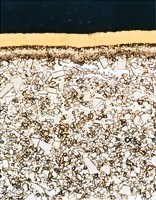
The coating itself acts as the interface between the workpiece and the cutting tool. Depending on the application, coatings can provide wear resistance, abrasive and crater resistance, build-up edge resistance, chemical resistance, or a simple reduction in friction that lowers cutting temperatures. Figure 2 (at right) shows an example of coatings engineered for a specific application.
The most commonly used coating materials and the properties they provide are:
- TiC: abrasive, flank and nose wear resistance,
- TiCN (titanium carbonitride): abrasive and some crater wear resistance,
- TiN (titanium nitride): some crater resistance, friction reduction, gold color, and a diffusion barrier,
- Al203 (aluminum oxide): crater and wear resistance, plus abrasive wear resistance at high cutting temperatures, and
- Al2O3/ZrO2 (aluminum oxide/zirconium oxide): best crater resistance, but softer than Al203.
There are four major coating technologies used in the cutting tool industry today. These are differentiated primarily by the temperature at which they operate. This is important because the coating temperature directly impacts substrate properties performance.
The most common coating technology is chemical vapor deposition, or CVD, which operates at a temperature of roughly 1,000°C. Nearly as common is physical vapor deposition, or PVD, which operates at the other end of the temperature spectrum in the 400°C range.
Between these two extremes are two other emerging coating processes that promise to enhance insert system performance. Plasma assisted chemical vapor deposition, or PCVD, is well accepted in Europe and is being explored in North America. PCVD operates in the 600°C range. Finally, medium temperature chemical vapor deposition, or MTCVD, is an emerging and promising technology that operates in the 800°C range.
The key factor to bear in mind is that the properties of both the coating and the substrate are changed by the application process. The same coating applied to the same substrate by different processes may in fact provide very different performance in the cut.
Different coatings are required for different materials. For example, it is critical to have a smooth coating—one that is more than simply wear- or crater-resistant—for hard-to-machine stainless steels and high temperature alloys. A smooth, thick coating is required when running steel and cast iron, too, because of the heat and wear. The PVD coating process produces a very smooth surface, while CVD coatings can be polished to achieve a smoother surface finish.
Coating thickness is critical for steel and cast iron because of the higher speeds at which they run. For high speeds, an oxide coating in combination with TiCN and proper thickness make an ideal combination. On the other hand, coating thickness is not as critical as smoothness for stainless steel and high temperature alloys.
Chipbreakers Or Top Form Geometries
With today's sophisticated insert shapes, the term "chipbreaker" no longer describes the contribution of this element to the insert systems. "Top form geometry" is a more precise term for the very complex shape seen on the cutting surface of a modern insert.
While chip control is still a major function, the top form geometry also serves to reduce cutting forces. Lower forces mean less heat, deformation and friction which enhance tool life and often improve workpiece size control and finish. Perhaps the best example of this is the use of "chipbreakers" on milling inserts. Generally speaking, milling chips tend to break themselves, but the other benefits of a well-engineered top form geometry are easily seen in reduced horsepower requirements and better parts. Many of today's high speed milling applications on relatively low horsepower machines would not be possible without effective top form geometries on the inserts.
Matching the chipbreaker to the application is very important. Valenite, a case in point, has 28 different chipbreakers for turning, some for roughing, some for general machining and some for finishing. Specialty geometries exist for certain metals, such as high temperature alloys and stainless steels. The Valenite SR chipbreaker is an example of this type of geometry. They are a positive-negative geometry, one with a small nose radius, perhaps only 0.004 inch. A very fine geometry is necessary to take very light cuts and control the chips in these types of materials.
Many shops think they don't need a chipbreaker for certain materials, such as gray cast iron and nodular cast iron, because the chips break on their own. These shops typically use flat top geometry for these materials because they have a lot of edge strength. However, we often recommend using a top form geometry for cast iron and nodular iron to reduce the cutting forces and minimize edge build-up.
Edge Preparation
In the past, most manufacturers offered only one or two standard edge preparations, or "hones," for any particular insert size and geometry. Today, however, it is recognized that the "hone" is really determined by the application for which the insert system is intended. An insert system intended for high speed finishing of steel has very different edge preparation requirements than one to be used for roughing, even though both may share the same basic geometry.
Ceramic and cermet materials also require edge preparation in the form of a "T-Land" geometry. Testing shows that very subtle variations in the width and angle of the "T-Land" can have substantial impact on tool life.
As a general rule, a heavier hone is necessary for continuous turning and milling of most steels and irons. Stainless steels and high temperature alloys, on the other hand, require a small hone or an up-sharp insert because of the build-up generated. Similarly, aluminum requires an up-sharp insert, also because of build-up. For cases involving a severe interrupted cut such as occurs in milling, a heavier hone or a "T-Land" is necessary.
Style And Nose Radius
Here, at least, conventional wisdom still prevails. Selecting a style with the greatest included angle will provide the strongest possible insert for the application. In general, a large nose radius provides better surface finish. These geometric factors, in conjunction with the toolholder, determine the effective lead angle, which impacts cutting force, and the resultant heat and wear that shorten tool life.
Not Just The Insert
Needless to say, it takes more than just the right insert to get optimum performance. The toolholder and the cutting fluid should also be considered part of the insert "system," even though these elements cannot be built in by the insert manufacturer.
In turning, the toolholder is the primary determinant of lead and rake angle, both of which can influence chip thickness, horsepower requirements, cutting forces and tool life. In milling the critical toolholder-related factors are radial and axial rake, which have the same effects found in turning applications.
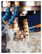
Choice of cutting fluids is one of the most overlooked factors in the performance of any metalcutting application. See Figure 3 (at left). Recent testing has shown that the choice of cutting fluid can have a substantial influence on both insert life and cutting system performance, especially on hard-to-machine materials like stainless steels and high temperature alloys.
It is extremely important, therefore, to follow the insert manufacturer's advice and instructions regarding toolholder selection and cutting fluids. Because the systems approach relies on a synergy between all of the elements, all of them are essential to enjoying the full benefits of an optimized insert.
Direction Of The Future
Laboratory testing and field experience have clearly demonstrated that the very subtle interaction of the seven elements of an insert cutting system can have an extremely large impact on application performance. Clearly, the direction for the future is in matching insert cutting systems more and more specifically to workpiece materials and cutting operations. MMS
About the author: Karl Katbi is product marketing manager at Valenite, Inc., Madison Heights, Michigan.
Related Content
OSG End Mills Provide High-Efficiency Milling
The company has expanded its range of end mills with two offerings for high-speed milling.
Read MoreSandvik Coromant Launches New Range of Solid End Mills
The CoroMill Dura range is designed for roughing and finishing with different engagements in all applications and materials.
Read MoreCeratizit's Updated Tooling Solutions Improve Machining Performance
The company has upgraded its EcoCut indexable inserts lineup, as well as introduced two new toolholding and workholding solutions.
Read MoreKennametal's Expanded Tooling Portfolio Improves Performance
The company has launch eight new products that expand on and support existing platforms across multiple applications.
Read MoreRead Next
Machining Success From Insert Failure
Indexable inserts do not last forever, but some fail prematurely. By selecting the right insert, shops can extend tool life.
Read MoreRego-Fix’s Center for Machining Excellence Promotes Collaboration
The new space includes a showroom, office spaces and an auditorium that will enhance its work with its technical partners.
Read MoreThe Future of High Feed Milling in Modern Manufacturing
Achieve higher metal removal rates and enhanced predictability with ISCAR’s advanced high-feed milling tools — optimized for today’s competitive global market.
Read More






.jpg;maxWidth=300;quality=90)


