Machining Success From Insert Failure
Indexable inserts do not last forever, but some fail prematurely. By selecting the right insert, shops can extend tool life.
Share


ECi Software Solutions, Inc.
Featured Content
View More
In an ideal world, indexable inserts wear evenly at a predictable rate without possibility of catastrophic failure. Well of course, that's not the reality of metalcutting.
Instead, the reality is that many shops find it worthwhile to select indexable inserts based on performance criteria that are application specific. Tooling vendors have created selection systems that make this selection process relatively painless.
This article is about one such insert selection process. It's from Valenite and uses a system that is based on insert failure analysis as the starting point for insert selection.
Using failure mode analysis, shops select an insert with characteristics to offset or postpone the often unobserved primary causes of insert failure. The system is based on extensive in-house testing and combines variables such as cutting conditions and type of cut.
All of this involves understanding material machinability and the interaction between an insert and the work. It leads to a selection method that groups material based on machinability rather than metallurgy.
To find out why inserts fail and how this knowledge can help shops make better decisions about what insert characteristics are needed for a given application, we talked to Karl Katbi, product marketing manager for Valenite (Madison Heights, Michigan).
Learning From Insert Failure
A shop's livelihood depends on the cutting tool. Much of the focus of a manufacturing operation is directed toward the successful application of cutting tool and workpiece material.
Profitability, hence business success, is derived from reducing the costs of manufacturing. This includes efficiency in the production of parts and extended life from consumable products such as indexable inserts. Selecting the right indexable insert is important.
Indexable insert manufacturers make literally thousands of specific cutters. Each is designed to perform best within a relatively constrained set of parameters. These include the workpiece material, machine tool feeds and speeds, coolant type and delivery.
Insert failure analysis is a method of determining how close a cutter and application match the optimum insert life span, as prescribed by the manufacturer. The idea is to look at the primary failure mode for various workpiece materials and select an insert that minimizes this primary failure mode.
For example, it is known that cutting some alloys of stainless steel produces build-up edge on the insert. This primary failure mode can result in premature, catastrophic failure of the insert.
Selecting an insert having the features designed to reduce build-up edge will extend insert life. Failure mode analysis is a method to help a shop specify an insert with substrate, coating, chipbreaker, edge preparation and coolant designed to reduce build-up edge enough for the insert to wear out at a consistent and predictable rate.
Material Difference
When insert selection is approached from a failure mode, workpiece material groupings tend to shift. For example steels are blue, stainless are yellow and gray, while ductile irons and aluminum are red. Materials are classified based on their machinability characteristics rather than chip formation type.
"In our failure analysis approach," says Mr. Katbi, "we group nodular and gray cast irons with aluminum alloys and other free-machining nonferrous materials. While the metallurgy of these materials is very different, we've found the primary cause for insert failures are similar with these materials."
Using machinability factors as the criteria for material classification puts failure mode selection at odds with the industry-standard material groupings.
"Most insert manufacturers use a standard color code for materials: blue, red and yellow," says Mr. Katbi. "The system is based on ISO standards that are derived from the types of chips created by the cutter. The failure mode analysis varies slightly from this standard because materials are grouped by their machinability characteristics."
Look Past The Obvious Failure
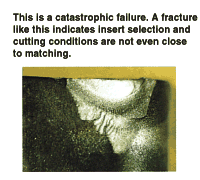
A worst-case insert failure occurs when the insert breaks in a cut. This is a catastrophic failure and can damage the workpiece, workholder and the machine tool. It's bad news for any shop.
Failure mode analysis looks at two types of insert failures -- primary and secondary. Primary is the initial or underlying problem, for example build-up edge. Being unaware of the primary failure mode will result in a secondary failure mode such as chipping which would constitute a catastrophic failure of the insert edge.
So, using failure mode analysis, the catastrophic fracture of an insert actually represents a secondary condition. But generally many shops look at the secondary failure mode as a starting point for correction. Based on the observation of a broken edge, the tendency may be to change inserts and use one with more radius on the edge or with a T-land ground in place.
That's the wrong analysis. In this case, the primary problem in this insert is build-up edge. As material welds itself to the insert cutting edge, machining pressure builds to a point where the edge breaks away, resulting in the secondary failure.
"Using failure mode analysis," says Mr. Katbi, "we look past the obvious chipped edge on the insert to find why the edge gave way. In the above example, the cure may simply be to increase cutting speed."
Usually the primary failure mode occurs gradually enough that periodic inspection of the insert will see evidence that failure is occurring. At this point, there is time to head off the catastrophic failure.
Inspection -- It's Good Practice
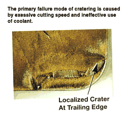
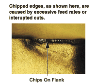
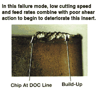
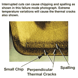
The accompanying photographs (Photograph Group 1 and Photograph 2) show what some of the primary failure modes look like. Seeing these tells a machinist that the insert is on its way to catastrophic failure. To avoid this, shops should make insert inspection part of the machining process.
Other symptoms a machinist can look for is surface finish deterioration or a drift out of size spec. Looking at the chips being formed can also give warning that a primary failure is occurring.
Cratering on an insert is an example. "When cratering is seen, there is a known set of responses that a machinist can use to eliminate the problem," says Mr. Katbi. "Usually cratering of the insert is caused by excessive cutting speeds, or inefficient use of coolant." To fix the problem, Mr. Katbi recommends to slow down speed and feed, select a harder carbide grade with an oxide coating, use a more positive rake chipbreaker and flood with coolant. Any of these steps alone or together will fix the problem.
It's important to realize that more than one mode occurs at a time. Often three or four may be at work simultaneously. Depending on the workpiece material, build-up, spalling, and thermal deformation may occur together.
Typically, one of them tends to get out of control before catastrophic failure occurs. The trick is to identify the one failure mode that is causing catastrophic failure and try to minimize it to make tool life more predictable.
Identifying the predominant primary failure mode allows the shop to index the insert before surface finish is lost, diameter size is lost or catastrophic failure occurs. "This why monitoring the machining operation on an incremental basis is so important," says Mr. Katbi. "If a shop gets 200 parts per edge, then the tool should be checked every 20 parts. If 20 parts are produced, check the edge every two or three parts."
Implementing procedures to recognize a primary failure mode before it escalates to a more serious failure level is a change that shops should consider if not already doing so.
Failure Mode Analysis For Coolant
In spite of industry trends to cut more applications dry, there are still many jobs that require coolant. Failure mode analysis can be applied to coolant selection.
Coolant has specific functions in machining. It can cool the work zone, lubricate the cutter chip interface and flush chips from the cutting zone.
It becomes another performance factor in the analysis of failure mode. "Too often shops don't give coolant selection a high priority," says Mr. Katbi. "It should be considered as part of the cutting system. By selecting the best coolant along with the optimum insert, shops can literally take the production and quality increases to the bank."
Banking On The Benefits
The object of failure mode analysis, or any indexable insert selection system, is to help shops use the best insert technology for a given application. Success is measured in increased cutter life with workpiece tolerances held well within spec.
Failure mode is based on the perishability of the indexable insert tool. The cutting life for these edges is finite. This selection method looks at the insert, machine tool, coolant and material as a system.
"The desired failure mode for an insert is even flank wear," says Mr. Katbi. "When an insert flank wears evenly, its useful life is predictable. Shops can expect consistent performance from the cutter, edge-to-edge and batch-to-batch."
Applying failure mode analysis to insert selection enables a shop to reduce or eliminate the primary causes of insert failure. Many of these primary failure modes go undetected in production until the insert fails catastrophically.
"When a shop understands why the insert broke, and that the breakage is a secondary failure caused by a primary problem involving the insert, material or cutting conditions, then selecting an insert by failure mode analysis makes sense," says Mr. Katbi.
The goal of Valenite's insert selection process is to provide shops with a method to select the insert that will deliver predictable tool life. They've done the work, and all a shop needs to do is follow the directions.
Insert Anatomy
There are four "parts" of an indexable insert. These are engineered to work in unison as a metal cutting system. The ability to manipulate any or all of these components is why there are so many different indexable inserts from which to choose.
The foundation for indexable inserts is the substrate. Generally it is made of a mixture of carbide and cobalt. It's analogous to the structure of a grinding wheel, with carbide taking the place of grit, and cobalt acting as binder.
Substrates can be formulated to give specific performance properties. An insert's toughness comes from the proportion of carbide to cobalt. Other materials such as titanium, tantalum, nickel or molybdenum may be added to the formula to provide specific performance characteristics.
On many indexable inserts the substrate is coated. These coatings are bonded to the substrate material using one of several deposition processes. The net result of each process, whether it is chemical vapor deposition (CVD), physical vapor deposition (PVD), or other, is to create a bond between the substrate and the coating.
Since the coating is the actual contact between the workpiece material and the insert, it too is formulated to provide specific performance properties. Lubricity, wearability and chemical compatibility are features that a coating brings to the insert system.
Many inserts are designed with bumps and grooves molded into the top. These chipbreakers help take some of the cutting pressure from the edge of the insert. They break continuous chips into smaller pieces. As a result, strings don't form.
Insert manufacturers provide a selection of chipbreakers designed for various applications. On grooving tools, for example, the chipbreaker is designed to crease the chip, making it smaller than the groove and thus allowing it to evacuate the cutting zone without scoring the sides of the groove.
How the cutting edge of an insert is prepared is the last factor of insert construction. Basically, edge preparation deals with the geometry of the insert edge.
To remove stock, a cutter edge must penetrate the workpiece surface and lift a chip. For shops trying to match optimum performance and long life there are choices. A very sharp cutting edge will more easily lift a chip but is prone to chipping and edge fracture. A small radius or a T-land step can be ground onto the edge to strengthen it by directing cutting forces into the body of the insert.
Related Content
Finding the Right Tools for a Turning Shop
Xcelicut is a startup shop that has grown thanks to the right machines, cutting tools, grants and other resources.
Read MoreHow to Mitigate Chatter to Boost Machining Rates
There are usually better solutions to chatter than just reducing the feed rate. Through vibration analysis, the chatter problem can be solved, enabling much higher metal removal rates, better quality and longer tool life.
Read MoreSelecting a Thread Mill That Matches Your Needs
Threading tools with the flexibility to thread a broad variety of holes provide the agility many shops need to stay competitive. They may be the only solution for many difficult materials.
Read MoreHow to Troubleshoot Issues With Tool Life
Diagnosing when a tool is failing is important because it sets an expectation and a benchmark for improvements. Finding out why gives us a clue for how to fix it.
Read MoreRead Next
Building Out a Foundation for Student Machinists
Autodesk and Haas have teamed up to produce an introductory course for students that covers the basics of CAD, CAM and CNC while providing them with a portfolio part.
Read MoreRegistration Now Open for the Precision Machining Technology Show (PMTS) 2025
The precision machining industry’s premier event returns to Cleveland, OH, April 1-3.
Read More5 Rules of Thumb for Buying CNC Machine Tools
Use these tips to carefully plan your machine tool purchases and to avoid regretting your decision later.
Read More




.png;maxWidth=300;quality=90)


