Stringer Solution
To reduce cost while improving quality and reproducibility, Airbus UK decided to implement a fully automated process able to machine a stringer complete. The existing production facility was stripped to its steel framework and adapted for the new process.
Share


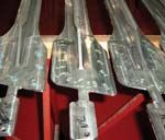
British aerospace company Airbus UK of Chester, Great Britain, traditionally has machined stringers up to 25 meters in length (for aircraft wings) using conventional milling machines. The complex geometry and precision free-form surfaces have required up to seven clamping operations. To reduce cost while improving quality and reproducibility, Airbus UK decided to implement a fully automated process able to machine a stringer complete. The existing production facility was stripped to its steel framework and adapted for the new process.
Planning and implementation for this new machining process fell to German Machine Tool company DS Technologie, or DST. The system designed by this company carries out a long series of steps involved in the production of lower stringers, beginning with a check of the contour of the T-shaped extruded aluminum profiles and ending with labeling of the finished stringer using a metal printer. At the system's heart are two DST "Ecoliner" machining centers using "Sprint Z3" five-axis machining heads. These machines are designed for a machining length of 31 meters, but only 25 meters is currently used. At present, no supplier can provide unmachined profiles any longer than this.
Five networked Sinumerik 840D controls from Siemens work to coordinate the numerous axes of motion the process employs. Throughout the process, video cameras, microphones and loudspeakers provide information for a control station located outside the protective housings of the machines. Other features of the automated installation include the following.
Laser-based identification. A laser is used to check the length and contour of unmachined profiles. This ensures that the correct profile has been loaded out of about 40 different variants. Orientation is also checked, because stringers for both the left and right wings have to locate at the machine zero.
NC crane. Workpieces move from laser measurement to machining using an NC gantry crane system more than 100 meters long. This crane system proved more flexible and accurate than the floor-based transport system originally intended for this process.
Modular hydraulic clamping system. On each of the two machines, profiles are clamped using an NC hydraulic clamping system. The system consists of eight units up to 3.5 meters long that can be individually controlled. Communications with the controls employ remote Profibus I/O from Siemens. The shafts supporting the clamping units in this system operate as direct axes, meaning they can be positioned with high accuracy.
High speed five-axis machining. To ensure that faults on the material surface are eliminated from the final part, stringer profiles include a heavy stock envelope—at least 6 mm all around the part. For these parts, 90 percent material removal is typical. To remove this material efficiently while generating the complex free-form surfaces, DST developed its new Sprint Z3 machining head specifically for this application. With three linear axes achieving rotary-axis pivoting using a tripod design, the head permits a range of motion of ±40 degrees for the spindle, which is capable of 24,000 rpm and 72 kW. This design makes the head relatively lightweight, so acceleration in the linear axes of up to 5 m/sec.² is possible.
Networked control and automation technology. The process uses a powerful control system. Each of the modular hydraulic clamping devices has up to ten axes of motion, each machine has five axes, and a tool change robot adds four axes more. The crane system also adds to control demands. Five networked controls coordinate all of this motion.
Industrial Ethernet (TCP/IP) supplies the appropriate programs using communications software at the CNC, and it also provides for the communications between separate sections. For the distant operator, up to 60 meters away, Siemens created the connection for a second operator panel through a multi-point interface with the help of repeaters.
Related Content
Cutting Part Programming Times Through AI
CAM Assist cuts repetition from part programming — early users say it cuts tribal knowledge and could be a useful tool for training new programmers.
Read MoreOrthopedic Event Discusses Manufacturing Strategies
At the seminar, representatives from multiple companies discussed strategies for making orthopedic devices accurately and efficiently.
Read MoreHow this Job Shop Grew Capacity Without Expanding Footprint
This shop relies on digital solutions to grow their manufacturing business. With this approach, W.A. Pfeiffer has achieved seamless end-to-end connectivity, shorter lead times and increased throughput.
Read MoreAutomated CAM Programming – Is Your Software Really Delivering?
A look at the latest automation tools in Autodesk Fusion 360 software and how forward-thinking machine shops and manufacturing departments are using them to slash delivery times and win more business.
Read MoreRead Next
5 Rules of Thumb for Buying CNC Machine Tools
Use these tips to carefully plan your machine tool purchases and to avoid regretting your decision later.
Read MoreRegistration Now Open for the Precision Machining Technology Show (PMTS) 2025
The precision machining industry’s premier event returns to Cleveland, OH, April 1-3.
Read MoreSetting Up the Building Blocks for a Digital Factory
Woodward Inc. spent over a year developing an API to connect machines to its digital factory. Caron Engineering’s MiConnect has cut most of this process while also granting the shop greater access to machine information.
Read More


.jpg;maxWidth=300;quality=90)


