Start With The Right Speeds And Feeds
Running rotary milling cutters at the proper speeds and feeds is critical to obtaining long tool life and superior results, and a good place to start is with the manufacturer's recommendations. These formulas and tips provide useful guidelines.
Share


By Ron Schneider, Ingersoll Cutting Tool Company
To compete in a world market, manufacturers need to run at ever higher levels of productivity. Whether cutting similar materials or materials of many different types, the goal must always be to obtain the highest metal removal rates possible within the limits of machine capability, cost economics and quality assurance.
Operating indexable carbide cutting tools outside the recommended ranges can result in poor performance. If feed rates are too slow, excessive heat may cause premature failure of the cutting edge. If feed rates are too high, the cutting edges may fracture, or worse yet, the cutter may fail catastrophically. If speed is outside recommended ranges, the cutting edges may experience build-up, excessive edge wear and cratering, poor workpiece surface finish, or chipping of the cutting edge.
To determine proper speeds and feeds for rotary milling cutters, several questions need to be answered:
- What is the workpiece material? The type of material to be milled has the most influence on where the speeds and feeds are set.
- What type of tool is being used? Face mills, end mills, slotters and drills all have specific operating guidelines concerning their use in various materials.
- What is the tool's diameter? Calculating the rate at which the cutting edge meets the workpiece is critical in determining the machine's speed. Formulas involving the cutter's diameter are used to establish the proper revolutions per minute (rpm).
- How effectively are the inserts arranged? As the cutter is rotated once, how many times does an insert appear at the same axial height and at the same radial location? All these inserts will share the cutting load as the cutter feeds across the workpiece.
- What is the depth and width of the cut? This information is needed to estimate how much power a given cut will require. Calculating the material removal rate will prevent spindle overload.
Materials
Steel, cast iron, aluminum, stainless steel, titanium and high temperature alloys all have different rates at which chips are formed most efficiently. Machinability ratings for specific materials are helpful when targeting a chip load for a particular operation, however, nothing beats prior experience when cutting uncommon metals.
Speed
The rate at which the carbide insert is presented to the workpiece is measured in surface feet per minute (sfm) or meters per minute (m/min.). For this article, we'll use sfm to refer to cutting speed.
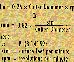
Surface feet looks at the velocity of the cutting edges as they impact the workpiece. Smaller diameter cutters need to have higher revolutions per minute since their distance to the center of rotation is less. Likewise, larger cutters need less rpm to propel their cutting edges at a given sfm. Using the cutter's diameter, sfm can be related to rpm:
These simplified formulas can also be used:
It is best to think of a particular material in terms of how fast (sfm) it can be machined using carbide indexable cutting tools. For example, aluminum is cut at 2,000 to 3,000 sfm whereas titanium is cut at 100 to 150 sfm.
Cutter manufacturers usually provide operating guidelines that help determine surface footage for a given cutter machining a specific material. Once sfm is established, rpm can be determined and the machine can be set.
Feed
Feed is the rate at which the cutter progresses into the workpiece. Most machine tools require this information in inches per minute (ipm) or millimeters per minute (mm/min.).
What type of cutter is being used? Face mills are typically able to take heavier chip loads than end mills in the same material. Face mills can run chiploads of 0.008 to 0.030 inch while end mills can run 0.004 to 0.015 inch feed per insert depending on material, operation and style of cutter. More information on the chip load or the feed per insert (fpi) is included in the operating guidelines for the cutter being used.
Insert Arrangement
How many effective inserts are in the cutter? How the inserts are arranged makes a difference because some arrangements provide more effective cutting inserts than others and will allow a higher feed rate.
This information helps determine the feed rate (ipm). If all the inserts are at the same radial location from the center line of the tool and also at the same axial height from the mounting surface, then all inserts are cutting the same path. Count the number of inserts in this cutter because all are effective inserts, typical of a face mill. The face mill shown on page 80 is this type of cutter.
In contrast, many end mills with long cutting lengths have multiple inserts and multiple flutes. Spaces in between inserts in one row are covered by inserts at a different axial position in the next row, as shown in Figure 1.
A few advanced end mill designs feature all-effective insert rows, in which each insert overlaps the next axially. In this case, the number of flutes is the same as the number of effective rows. See Figure 2.
To determine the feed rate, use the following formula:
ipm = fpi x #eff x rpm
Where:
ipm = inches per minute
fpi = feed per insert
#eff = number of effective inserts
rpm = revolutions per minute
Operating guidelines help you choose the fpi for the cutter and material. Multiply the fpi by the number of effective inserts and then by the rpm. The result is the feed rate (ipm).
Do not overload the spindle by taking a cut that exceeds the available horsepower. To avoid overload, calculate the material removal rate (mrr). The mrr is the volume of material removed (in cubic inches) per minute.
mrr = ipm x woc x doc
Where:
mrr = material removal rate
woc = width of cut
doc = depth of cut
ipm = inches per minute feed rate
After determining the mrr, refer to Table I, unit horsepower, which shows the amount of horsepower needed by a machine to remove one cubic inch of a specific material.
mrr x unit hp = hp required by machine
If the horsepower available cannot handle the mrr, revise the depth of cut or the width of cut, but do not reduce the feed rate. Milling cutters with insufficient feed tend to generate heat in the workpiece and tool life will be adversely effected.
Starting Points
Although exact speeds and feeds can be calculated for a given operation, these values are starting points at which the cutter should operate successfully. The machine may need to be run a little faster or slower depending on conditions for that job. A cutter's geometry and insert sharpness also impact cutting dynamics. However, acceptable results can generally be expected if the manufacturer's operating guidelines are followed and the machine is set properly for the cutter and material.
| Table I | |
| Material | Unit Horsepower |
| Aluminum | 0.25 |
| Brass (Soft) | 0.33 |
| Brass (Hard) | 0.50 |
| Bronze (Hard) | 0.71 |
| Bronze (Very Hard) | 1.54 |
| C1 (200 BHN) | 0.67 |
| C1 (Over 200 BHN) | 1.00 |
| Malleable Iron | 0.80 |
| Steel 100 BHN | 1.25 |
| Steel 150 BHN | 1.43 |
| Steel 200 BHN | 1.54 |
| Steel 250 BHN | 1.82 |
| Steel 400 BHN | 2.00 |
Related Content
The Future of High Feed Milling in Modern Manufacturing
Achieve higher metal removal rates and enhanced predictability with ISCAR’s advanced high-feed milling tools — optimized for today’s competitive global market.
Read MoreSelecting a Thread Mill That Matches Your Needs
Threading tools with the flexibility to thread a broad variety of holes provide the agility many shops need to stay competitive. They may be the only solution for many difficult materials.
Read MoreHow to Mitigate Chatter to Boost Machining Rates
There are usually better solutions to chatter than just reducing the feed rate. Through vibration analysis, the chatter problem can be solved, enabling much higher metal removal rates, better quality and longer tool life.
Read MoreQuick-Change Tool Heads Reduce Setup on Swiss-Type Turning Centers
This new quick-change tooling system enables shops to get more production from their Swiss turning centers through reduced tool setup time and matches the performance of a solid tool.
Read MoreRead Next
5 Rules of Thumb for Buying CNC Machine Tools
Use these tips to carefully plan your machine tool purchases and to avoid regretting your decision later.
Read MoreSetting Up the Building Blocks for a Digital Factory
Woodward Inc. spent over a year developing an API to connect machines to its digital factory. Caron Engineering’s MiConnect has cut most of this process while also granting the shop greater access to machine information.
Read MoreRegistration Now Open for the Precision Machining Technology Show (PMTS) 2025
The precision machining industry’s premier event returns to Cleveland, OH, April 1-3.
Read More


