Managing Grinding Forces and Abrasive Sharpness
Successfully removing material with a grinding wheel requires sharp grains, but even dull grains can serve a purpose if they’re carefully controlled.
Share


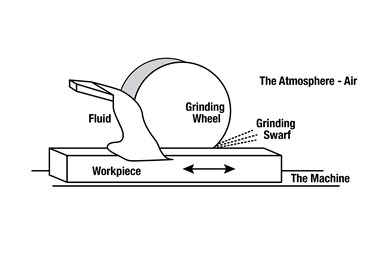
Cutting, plowing and sliding take place simultaneously in the grinding zone. Understanding the effects of these interactions better enables machinists to optimize the balance of these interactions in grinding applications. Image courtesy of Norton | Saint-Gobain Abrasives.
Sharp grinding wheel grains are essential for removing material from a workpiece. Understanding the microscopic and macroscopic interactions in the grinding zone is essential for fully optimizing the grinding process and eliminating quality issues. This article will discuss these interactions, as well as methods for maintaining grinding wheel sharpness and optimal performance.
Cutting
Each individual abrasive grain on a grinding wheel acts as a cutting tool. As the grinding wheel applies forces to remove material, the workpiece applies resistance forces to the wheel.
When using vitrified or metal-bonded grinding wheels, these resistance forces lead to fracturing of the abrasive grain from the bond. In the case of organic- and resin-bonded wheels, the heat produced from the grinding interaction releases dull abrasive grains over time, exposing the new sharper grain beneath it.
As the abrasive grains encounter the workpiece, other microscopic interactions take place beyond the chip-making process. For example, when dull grains are not released efficiently or the grain does not fracture properly, these dull grains begin plowing and sliding rather than removing material.
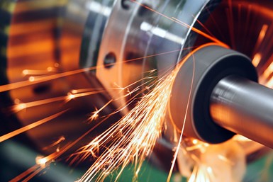
Plowing and sliding from dull grains increases heat in the grinding zone and leads to swarf. Properly controlled, however, these interactions can enhance the surface finish of the workpiece.
Plowing
During the grinding process the workpiece material undergoes localized deformation, with this deformed material being displaced later. The localized deformation between the workpiece and the abrasive is called plowing. The plowed material slides — more on that later — on the grinding wheel surface prior to leaving the grind zone. The microchips produced by this deformation can clog the pores of the grinding wheel. The chances of this problem are increased by factors such as insufficient grain exposure, extremely hard wheel bonds and gummy workpiece material.
While uncontrolled plowing can cause issues, planned plowing can improve surface finish. Plowing increases the Specific Grinding Energy (SGE), which is the energy required to remove a unit (cubic inch or millimeter) of workpiece material. SGE serves as a measure of efficiency of the grinding process and is calculated from the grinding power by the following equation:
Specific Grinding Energy (SGE) = (Grinding Power) ÷ (Material Removal Rate)
The symbol for SGE is U’ and the units of specific energy are Btu/in3 and J/mm3.
As shown in the equation above, specific energy is inversely proportional to material removal rate and directly proportional to grinding power. Plowing decreases the material removal rate and increases grinding power, both of which increase the specific energy. Increasing SGE elevates heat in the grind zone, so uncontrolled plowing may cause thermal damage to the workpiece.
Threshold power also increases during plowing, corresponding to higher forces needed to fracture the abrasive. Threshold power is a function of friction and is not associated with the making of an active chip. As with SGE, increased forces and friction raise the temperature in the grind zone and heighten the risk of thermal damage.
Controlling plowing in the finish pass, however, can result in a finer surface finish as the wheel glazes over the workpiece material. Controlled plowing can also correct small dimensional inaccuracies as the wheel knocks out high spots in the workpiece.
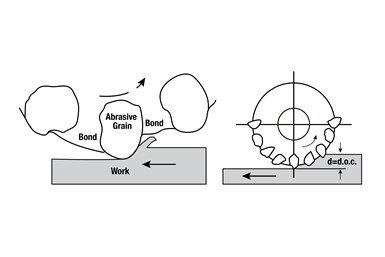
In cutting interactions, an abrasive grain penetrates the workpiece material and removes a chip. When the grain fails to penetrate the material or the bond begins to meet the workpiece surface, plowing and sliding can occur. Image courtesy of Norton | Saint-Gobain Abrasives.
Sliding
Plowing action will eventually lead to sliding. During sliding, the abrasive cannot buildup sufficient force to overcome resistance and penetrate the material, leading to an inability to create chips. The high resistance forces also result in the erosion of the wheel’s bond, which then translates to loose abrasives in the system. Swarf forms from a combination of impurities in the system, loose abrasive grain, bond and microchips.
The process of sliding causes loading of the wheel. Eventually the wheel loads up enough to interfere with the cutting process and degrade the surface finish. Factors that lead to premature sliding include incorrect dressing or truing of the wheel, blocky grain that cannot penetrate the workpiece, workpieces that are too hard for the selected grinding wheel, and wheel bonds that are too hard.
Sliding can cause major thermal damage due to significant increases in threshold forces and SGE. Sliding can also create normal forces — the downward pressure applied to penetrate material hardness — exceeding the grinding forces, a problem which leads to dimensional inaccuracies. Just like plowing, sliding produces finer surface finish, but thermal damage can cause the quality of the surface to be completely unacceptable.
Maintaining Sharpness of a Grinding Wheel
Here are five steps for maintaining a sharp grinding wheel and avoiding the issues caused by plowing or sliding:
- Use the right abrasive type for the material. The abrasive’s friability (fracturing ability) should be considered when choosing a grinding wheel. Maintaining abrasive sharpness is extremely important when penetrating tough material.
- Choose the right bond type and grade hardness. If the wheel is too hard, it will not release the grain.
- Verify that the grinding wheel is paired with the correct dressing tool, and optimize the dressing parameters and frequency. Dressing the wheel will help to maintain sharpness and minimize loading.
- Analyze the coolant system. Coolant type, pressure, volume, concentration, lubricity and location are extremely important in minimizing forces and keeping the wheel sharp, as is the choice of coolant nozzle. When properly used, coolant removes swarf and maintains temperature, minimizing the risk of thermal damage.
- Ensure that grinding parameters are optimized for the process. Don’t push the wheel harder than its capability.
Related Content
Inside the Premium Machine Shop Making Fasteners
AMPG can’t help but take risks — its management doesn’t know how to run machines. But these risks have enabled it to become a runaway success in its market.
Read MoreBallbar Testing Benefits Low-Volume Manufacturing
Thanks to ballbar testing with a Renishaw QC20-W, the Autodesk Technology Centers now have more confidence in their machine tools.
Read MoreWhere Micro-Laser Machining Is the Focus
A company that was once a consulting firm has become a successful micro-laser machine shop producing complex parts and features that most traditional CNC shops cannot machine.
Read MoreQuick-Change Tool Heads Reduce Setup on Swiss-Type Turning Centers
This new quick-change tooling system enables shops to get more production from their Swiss turning centers through reduced tool setup time and matches the performance of a solid tool.
Read MoreRead Next
Registration Now Open for the Precision Machining Technology Show (PMTS) 2025
The precision machining industry’s premier event returns to Cleveland, OH, April 1-3.
Read MoreSetting Up the Building Blocks for a Digital Factory
Woodward Inc. spent over a year developing an API to connect machines to its digital factory. Caron Engineering’s MiConnect has cut most of this process while also granting the shop greater access to machine information.
Read MoreBuilding Out a Foundation for Student Machinists
Autodesk and Haas have teamed up to produce an introductory course for students that covers the basics of CAD, CAM and CNC while providing them with a portfolio part.
Read More









.jpg;maxWidth=970;quality=90)