Four New High-Performance Milling Techniques for 3D Machining
Sponsored ContentWith many 3D milling applications demanding both shorter cycle times and smoother surface finishes, it’s time to review how you go about programming and machining parts. These four strategies will let you rough dramatically faster and achieve astonishingly fine surface finishes.
Share
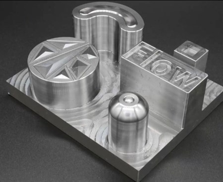
Siemens used this test part to demonstrate new state-of-the-art milling techniques. It is made of tool steel hardened to 54 HRC and was machined on a Micron HPM 800U machining center.
Something most shops doing intricate 3D machining – such as molds, dies and medical parts – have to live with are long cycle times and laborious post-machining finishing processes. Whether it’s EDMing and benching a mold cavity or hand-finishing medical implants, these processes take a lot of time and effort. Add in the time and skills it takes to program geometrically complicated workpieces, and making these parts can become a very inefficient and expensive proposition.
High speed machining techniques have certainly helped shops get closer to final form on machining centers in less time, but there’s still plenty of room for improvements that will yield shorter lead times, better quality components and lower overall costs.
Manufacturing software developer Siemens Digital Industries Software has made the continuing development of new machining capabilities with its NX CAM software a priority over time and has a lot to say about what strategies will best enhance both roughing and finishing of 3D parts. They’ve also developed a range of capabilities that automate and speed the programming process itself.
Four new such capabilities are shown below. Short narrated videos about this advanced CNC programming and machining technology are included too. Here’s more on techniques that can substantially enhance your 3D machining capabilities.
Rough up to 80% Faster with Adaptive Milling
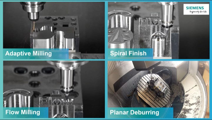
Whether dealing with a mold cavity or a prismatic shape, the fastest way to remove material is often with NX CAM’s high-speed roughing cycle – Adaptive Milling. With this advanced cutting technique you reduce the radial depth of cut (stepover) to less than 25% of the tool diameter but significantly increase the axial depth of cut. Because chip thickness is now much smaller than the centerline feed per tooth, you can substantially increase the feed rate. This results in light, fast cutting action with faster metal removal rates, which can reduce machining time by up to 80% in some cases. It also generates less heat and vibration in the cutting zone, which in turn enables more secure, predictable cutter wear.
VIDEO: Adaptive milling can reduce roughing times by as much as 80%.
The key to making this process work is the ability to maintain constant cutting force throughout the roughing routine. For example, running a tool into a corner in a conventional pocketing cut suddenly increases material engagement and causes cutting forces on the tool to spike. This and other rapid changes in cutting force create shocks that can lead to chipping, poor surface finish and substantially reduced tool life.
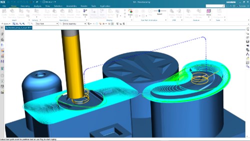
NX CAM’s Adaptive Milling smooth toolpaths automatically maintains a consistent chip load, enabling high material removal rates (MRR) and extended tool life.
With Adaptive Milling the toolpath automatically maintains a consistent chip load which results in faster, smoother cutting. The technique is particularly beneficial in roughing cores and cavities in tool steels as well as pocketing in heat resistant super alloys (HRSA) such as Inconel and titanium. It combines high metal removal rates in these difficult materials and longer, more predictable tool life.
With its latest release of NX, Siemens has enhanced this feature with adaptive pillar cutting. When milling conventionally with a spiral collapsing pattern, after milling down the adjacent regions of a protruding part feature you are often left with work hardened surfaces that are difficult to program and machine to final form, forcing a slower machining process with reduced tool life.
VIDEO: With adaptive pillar milling protruding features are automatically identified and generated with an efficient helical milling process. Tools provided by FRAISA
With adaptive pillar cutting these workpiece features are machined with a high-speed helical motion with high entrance speeds and ramp angles. To speed part programming, the software automatically identifies workpiece features appropriate for the process and combines all pillar cutting operations into one continuous cycle.

The rest milling function automatically identifies remaining material and machines it with a smooth, continuous toolpath.
There is also an enhanced rest milling function that leverages smooth transfer moves. The software automatically identifies remaining material and connects each pass with a smooth transition which enables use of higher speeds. The optimized toolpath accelerates machining through the reduction of non-cutting time. It reduces programming time as well.
Spiral Finishing Cuts Cycle Times while Generating Extremely Fine Surface Finishes
Spiral Finishing also reduces cycle time by cutting as much material as possible with continuous in-cut toolpaths interrupted only by retract and engage motions to reach different workpiece features. Within a pocket, for example, there will be a single continuous in-cut motion until the semi- or final-finishing of that feature is complete.
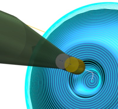
Spiral Finishing’s continuous in-cut toolpath results in efficient machining and mirror-like surface quality.
Spiral Finishing is easy to program in NX because you just have to select the areas to be finished and the tool, and then the software does the rest. Besides being faster, the continuous toolpath results in smoother surfaces. It is exceptionally applicable to micro machining applications. As the video below shows, Spiral Finishing can be applied to generate extremely fine features to exact dimensional standards. In a final finishing example in the video, a 2 mm (0.078”) ball mill is used with 0.07 mm (0.0028“) stepovers at a feed rate of 1188 mm per minute (46.8 ipm). The features being generated are only 0.5 mm (0.020 in.) in height.
VIDEO: Spiral finishing is an extremely efficient way to generate fine features with excellent surface finishes.
Flow Milling Enables Machining with Extraordinary Tolerances and Surface Finishes
Flow Milling takes achievable 3D finishing tolerances to a whole new level, which can be measured in microns. In the example below, the tool is only 0.5 mm (0.0236”) in diameter yet fed at 713 mmpm (28 ipm) with stepovers of 0.02 mm (0.0008”). This is truly remarkable considering that such a hard material (54 HRC) is being cut at this rate with such a small diameter tool. Not only can this process accurately generate extremely small workpiece features, it also results in extraordinarily high surface finishes.
Flow milling creates extremely accurate toolpaths for tiny workpiece features.
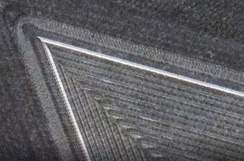
Flow milling finish cut magnified 25x.
Flow milling should be of particular interest to mold makers because it allows you to machine features, such as corners of pockets, that otherwise would have to be finished with sinker EDM, which can be a time-consuming process. As this image shows under 25x magnification, extremely sharp features can be generated that were not practical to machine in the past with conventional milling techniques.
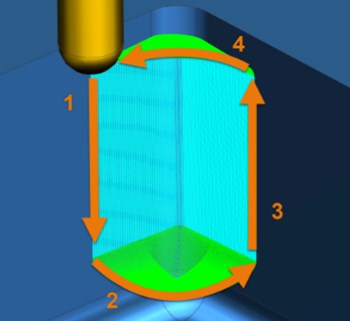
“Outside-in” corner milling technique
For very tight corners, rather than using a Z-level flow machining strategy, Siemens discovered it was better to use an innovative process where the tool is fed down one side of the pocket corner and the up the other side, with stepovers progressing toward the center. This “outside-in” alternate machining strategy results in both shorter cycle times and better surface finish. And it can eliminate the need to machine electrodes and the slow burn of EDM to finish a cavity.
VIDEO: “Outside-in alternate” Flow Milling technique can be used to generate sharp pocket corners that otherwise would require sinker EDM for finishing.
Planar Deburring Automation Saves Valuable Programming Time
Deburring is one of those nagging operations that can be difficult and time consuming to program in complicated parts which is why so many shops continue to deburr with post machining processes. Planar Deburring is a new NX function that greatly simplifies the programming process allowing a fully deburred part to be completed right in the machining cycle. It’s particularly useful for parts such as investment castings where edges must be cleaned up as well as other machined features.
Planar Deburring automatically detects edges and generates deburring routines even for complicated parts with a simple programming task.
All you need to set for a Planar Deburring routine is the chamfer size and chamfer Z-axis offset. The software will automatically detect and create toolpaths to machine all edges of a part, even with very complicated workpiece geometries. It also automatically checks for collision points with adjacent features. To further automate the programming it can be set to ignore holes which have already been deburred in the holemaking process so they don’t have to be manually excepted from the program through manual editing or create a redundant machining process.
While all the videos in this article demonstrate these machining strategies on a 3-axis cuts, each can also be performed of 5-axis machining centers. In either case they illustrate new ways to get a better return on your considerable investments in machining and programming technology as well as the skilled people who use it. Moreover, with these innovative cutting methods you can achieve levels of accuracy, surface finish and efficiency on a machining center that were unthinkable only a few years ago.
You can try these and other advanced CNC programming capabilities by launching the free cloud-based NX CAM trial in your browser.
Go here for more information on Siemens NX CAM software.
View the webinar: Digital Machine Shop: Boost Your Productivity with High-Performance Milling.
