
Desktop 3D Scanner Captures Part Shapes
This desktop laser scanning system allows 3D objects to be digitized so that the data can be used to create part geometry for tool path generation. The system's ease of use and low cost make reverse engineering available to machine shops that could not previously access this technology.

Share


Hwacheon Machinery America, Inc.
Featured Content
View More


.png;maxWidth=45;format=webp)
DMG MORI - Cincinnati
Featured Content
View More

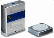
NextEngine’s desktop scanning unit is about the size of a cereal box. It controls the AutoPositioner roundtable to automate part indexing for scanning multiple views.
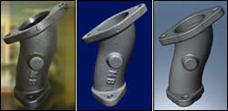
From points to part: the left photo shows a part to be scanned. The middle image shows a 3D mesh model generated from multiple scans aligned and blended in the system’s basic software. The right image shows the geometry as fully rendered in 3D CAD with parametric information.
Scan it. Cut it. That’s the approach many shops would like to take. A new desktop laser scanning system promises to make that a practical reality at low cost. The system allows 3D objects to be digitized so that surface data can be used to create part geometry for toolpath generation. The NextEngine Desktop 3D Scanner from NextEngine Inc. (Santa Monica, California) uses a set of laser “eyes,” digital camera technology and image sensors to capture scan data from multiple, triangulated views. The system’s special software assembles and manipulates the data to create a 3D model suitable for use in a CAM system.
Scanning systems for reverse engineering have been available for years. What sets this new system apart from existing systems is that it is priced and packaged like a consumer electronics product. The hardware consists of a scanning unit (about the size of a cereal box) and a turntable that automates part positioning for scanning. The user interface software, ScanStudio Core, operates the scanner and the turntable. It is priced at $2,495. Two software options, ScanStudio Pro and RapidWorks, provide further capabilities and are priced in the same range.


For the machine shop, desktop scanning is a benefit when the machining process starts with a part—a prototype, a pattern, a model or a free-form “organic” shape carved in the studio or found in nature. CNC machines are designed to produce parts as the end product. The physical object cut from metal is the output. But CNC machines also require input, the numerical part program that gives the proper commands. Digital laser scanning helps bridge the gap from “start part” to end part by providing the “art” (shape geometry) in the middle. According to developers, the desktop scanner makes 3D scanning technology available to virtually any machine shop.
The scanning unit uses arrays of low-power lasers that sweep across an object while 3-megapixel cameras capture scanned data. Multiple sweeps and multiple positionings of the object are usually required to gather a complete 3D scan. The various passes can be displayed and merged in the PC software. Objects with matte white surfaces are easiest to scan; objects with shiny black surfaces are more difficult. The latter may require a powder dusting to reduce reflectiveness.
Objects the size of a soda can or smaller can be scanned in the “macro mode,” while objects as large as a shoebox can be scanned in the “wide mode.” The roundtable can be used to index smaller objects automatically for multiple scans. Large objects may have to be repositioned by hand. Developers say that, theoretically, there is no limit to the size of the object because any number of scans can be stitched together. Parts fitting within the "wide mode" can be scanned and aligned with one click. Scans from larger parts are semi-automatically aligned with “virtual beads” that the software can use to locate and connect common points in the scanned data for merging. Regardless of the merging process, blending and trimming overlaps is automated, thus speeding what might otherwise be a tedious process.
Scan data can be used to create file formats in three categories—mesh, surface and solid—that correspond to the level of software acquired by the user. For example, the standard software that comes with the system is adequate for STL formats that can be exported to a CAM system for basic machining. Most shops will be interested in the surface or solid file capabilities because they provide geometry comparable to the models shops often use as input to CAM.


Related Content

How to Mitigate Chatter to Boost Machining Rates
There are usually better solutions to chatter than just reducing the feed rate. Through vibration analysis, the chatter problem can be solved, enabling much higher metal removal rates, better quality and longer tool life.
Read More
ERP Provides Smooth Pathway to Data Security
With the CMMC data security standards looming, machine shops serving the defense industry can turn to ERP to keep business moving.
Read More
Continuous Improvement and New Functionality Are the Name of the Game
Mastercam 2025 incorporates big advancements and small — all based on customer feedback and the company’s commitment to keeping its signature product best in class.
Read More
Orthopedic Event Discusses Manufacturing Strategies
At the seminar, representatives from multiple companies discussed strategies for making orthopedic devices accurately and efficiently.
Read MoreRead Next

5 Rules of Thumb for Buying CNC Machine Tools
Use these tips to carefully plan your machine tool purchases and to avoid regretting your decision later.
Read More
Building Out a Foundation for Student Machinists
Autodesk and Haas have teamed up to produce an introductory course for students that covers the basics of CAD, CAM and CNC while providing them with a portfolio part.
Read More
Registration Now Open for the Precision Machining Technology Show (PMTS) 2025
The precision machining industry’s premier event returns to Cleveland, OH, April 1-3.
Read More