
CNC Machine Programming: Dealing with Spindle Probe Results in Real Time
There are several situations in which a CNC programmer must work with spindle probe results in the G-code program itself. Here are some strategies to consider.
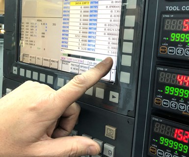
.jpg;width=70;height=70;mode=crop;format=webp)
Share


Hwacheon Machinery America, Inc.
Featured Content
View More

Autodesk, Inc.
Featured Content
View More


There are two general types of machining center spindle probe applications: those that can be handled separately from the machining G code program and those that cannot.
Consider, for example, the need to measure a program origin in each axis and enter the results into fixture offset registers. This is done one time per setup, and the G-code program that machines the workpiece need not be involved.


The more challenging case is when probing results must be dealt with in real time during the execution of every CNC cycle and from within the G-code program. It can be especially problematic if you are using a CAM system to generate G-code programs since some CAM systems are not designed to generate probing commands, let alone deal with the results of probing.
There are at least four situations in which machining center spindle probes can help in real time.
When can machining center spindle probes help a CNC programmer?
- During setup: Maybe raw material comes in the form of castings or forgings. An operator may not be able to perfectly load and locate every raw workpiece. When the program is activated, a probe will first determine the workpiece’s angular orientation. The result is used to generate a corresponding coordinate rotation command that will be executed before machining is done.
- When error trapping: This technique is used to stop a program’s execution when a disruptive issue is found. The related logic in the G code will need to deal with at least two possibilities: If the problematic issue is not detected, the program can continue; if the issue is detected, the program must be stopped with an informative alarm generation command.
- Prior to machining: Spindle probes can help determine how machining must occur. The amount of cast raw material on a machined surface, for instance, may vary from one workpiece to the next. A CAM system can generate the motion commands for one of the roughing passes, but the logic required to determine and make the appropriate number of passes using the intended depth per pass must be included in the G-code program.
- During in-process gaging: Measuring with spindle probes for quality control purposes is controversial. One commonly accepted rule of thumb is that you shouldn’t measure the workpiece on the same machine that produced it. That said, you can use spindle probes to measure critical surfaces for the purpose of trial machining. After semi-finishing, the probe can determine how much more material must be machined so that offsets can be adjusted. The related logic commands must be included within the G-code program.
Spindle probe manufacturers provide a series of special programs (such as custom macros for FANUC controls) designed to get probing results. A simple calling command can, for example, tell the probe to find the location of a surface in any axis, the width of a slot, the height of a boss, the center of a hole, etc. Some CAM systems are designed with probing in mind and can create the necessary custom macro calling commands.
Even so, you will still be on your own to deal with the results the probe provides. Take a lesson from probe manufacturers: Don’t incorporate all of the related logic and motion commands into your G-code program. Instead, create your own series of custom macros to deal with probing results. This will minimize the number of commands you must include in your machining programs and keep you from duplicating effort when similar actions must be taken on multiple workpieces. One error-trapping custom macro, for instance, may work for any number of machining programs.
With FANUC custom macros, probe manufacturers store probing results in #100 series common variables. Consider, for instance, a cast surface that is varying in the Z (depth) axis from one workpiece to another. After probing, this Z position may be stored in common variable #133. Let’s say that this cast surface is supposed to be 1.1 inch above the program zero surface (finished to 1.0 inch), but it varies between 1.05 to 1.3 inches. After probing, the value of common variable #133 will range from 1.05 to 1.3.
After the machining program probes the surface, your simple calling command could look like N200 G65 P9501 V#133 B1.3 S1.05 Z1.0 Q0.05, where:
- G65 is the G code used to call a custom macro;
- P9501 is the custom macro program number;
- V is the variable number from the probing result;
- B is the big (high) limit for stock amount (alarm will sound if higher);
- S is the small limit for stock amount (alarm will be sounded if lower);
- Z is the finished surface Z-axis coordinate; and
- Q is the depth per pass for roughing.
There could be more input variables depending on the application, such as those related to the shape of the surface to be machined if it is not generated by the CAM system. The calling command must provide the rough machining custom macro with the information needed to appropriately perform the roughing operation, regardless of how many passes are required.


Related Content

How to Determine the Currently Active Work Offset Number
Determining the currently active work offset number is practical when the program zero point is changing between workpieces in a production run.
Read More
Tips for Designing CNC Programs That Help Operators
The way a G-code program is formatted directly affects the productivity of the CNC people who use them. Design CNC programs that make CNC setup people and operators’ jobs easier.
Read More
Troubleshooting Differences in Programming Methods, Machine Usage
Regardless of the level of consistency among machines owned by your company, you probably have experienced consistency-related issues. Here are some tips to help solve them.
Read More
Strange But True: Odd Things That Happen With CNCs
These oddities in the way a CNC naturally behaves can help explain some rather unusual situations that may occur during machining.
Read MoreRead Next

Building Out a Foundation for Student Machinists
Autodesk and Haas have teamed up to produce an introductory course for students that covers the basics of CAD, CAM and CNC while providing them with a portfolio part.
Read More
Setting Up the Building Blocks for a Digital Factory
Woodward Inc. spent over a year developing an API to connect machines to its digital factory. Caron Engineering’s MiConnect has cut most of this process while also granting the shop greater access to machine information.
Read More