CAD/CAM Systems Drive Efficient Porting Routines
Delcam’s PowerShape design software and PowerMill machining software help this performance racing component manufacturer meet targets for accuracy and efficiency during engine porting operations.
Share


Takumi USA
Featured Content
View More

ECi Software Solutions, Inc.
Featured Content
View More

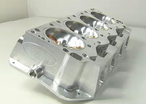
One of the more difficult operations performed by manufacturers of performance racing components is porting—that is, machining the ports that direct airflow to and from the engine’s cylinders. These inlet and exhaust ports involve complex, difficult-to-access internal geometries with curves, tapers and demanding surface finish requirements. Efficiently performing this specialized application typically involves certain types of equipment, including lollipop cutters that can reach difficult-to-access areas within the ports and five-axis machine tools. However, just as important to efficiency are the tools employed before machining actually begins—the software used to design the ports and the software used to program the tool paths.
For that, MBE Cylinder Heads and Manifolds relies on the PowerShape design software and PowerMill machining program from Delcam (Windsor, Ontario). Head programmer Mark Olson says PowerShape’s powerful surfacing engine and PowerMill’s automatic porting routines are key to obtaining the required accuracy and surface finish while keeping cycle times low and avoiding collisions and other problems. "I’ve used a lot of programs in my career—which began in 1970—and this is the smartest software that I’ve ever used," he notes.
Founded in 1997 by Matt Bieneman, MBE is located in the heart of America’s racing country in Mooresville, North Carolina. Mr. Bienenman created a team of specialists hand-picked from the best in the industry and was equally particular about his selection of equipment and software. MBE credits his selectivity for the levels of quality and engineering that have made the shop the preferred choice for leading race teams and engine builders throughout the United States, Australia and Canada. Customers include teams from dirt racing and drag racing, as well as competitors in tractor- and truck-pulling events.
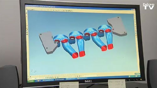
The first step of the porting process is manifold design, which the company performs manually. Once happy with the design, the company digitizes the ports, chambers and whatever else needs to be machined and imports the data into PowerShape, Delcam’s hybrid modeling CAD program. There, programmers refine the design using the software’s surfacing engine. "I haven’t yet found anything else that’s as useful for manipulating the surface data into exactly the shapes I need," Mr. Olson says.
After perfecting the model, programmers move the design into PowerMill, which is used to either machine ports directly from solid material or to finish-machine cast engine components. Mr. Olson says the transparent interface between the two software systems makes it fast and easy to cut and paste geometry from one to the other without conventional importing and exporting.
For MBE, the primary benefit of PowerMill is its ability to optimize the machining sequence. Mr. Olson explains that programmers employ three strategies for port machining: three-axis cutting, continuous five-axis cutting and positional five-axis cutting. (Also known as 3 + 2 machining, positional five-axis differs from continuous five-axis in that the tool is locked at a certain angle by the two rotational axes during a three-axis routine.) With most machine tools, three-axis and positional five-axis routines tend to offer greater rigidity, which reduces vibration and enables more accurate cuts at higher speeds. For that reason, the shop prefers to use these options whenever possible.
However, certain areas of the engine ports require continuous five-axis machining. PowerMill automatically divides the process between areas that are accessible with three machine axes and those that require five, Mr. Olson says. This ensures that as much material as possible is removed via three-axis and positional five-axis operation and that continuous five-axis machining is employed only where necessary. As a result, the shop can reduce cycle time while meeting surface finish requirements.
The port machining sequence uses a spiral motion for theroughing cuts. For finish machining, the operator can choose between a spiral or plunging approach. The spiral approach produces cusps that run perpendicular to the flow of gas through the port, increasing turbulence. In contrast, cusps produced by the plunging technique run parallel to the flow direction. This speeds passage of the gas mixture.
"PowerMill has a very powerful automatic porting routine—this is one of the major reasons why we purchased it," Mr. Olson says. He adds that additional features of PowerMill further contribute to MBE’s ability to achieve a quality surface finish, which is especially important for engine port performance. "It keeps the edge of the tool in contact with the port, as opposed to the tip of the tool. Cutting with the edge of the tool gives you much better surface finish."
Moreover, the software’s port machining strategies provide a great deal of control over point distribution, he notes. Increasing the number of points in the tool path provides more even machining with less vibration and more consistent tool loads. In addition to improving surface finish, this reduces tool wear. The software also automatically divides the CAD model to create the surfaces that will be machined from either end of the port. The user can specify the length of overlap between the two sets of tool paths to ensure a smooth transition between the two areas.
Finally, Mr. Olson notes that since adopting PowerMill, the shop has never experienced interference or a collision—despite consistently dealing with clearances as small as 0.015 inch. In part, this is due to the fact that the software "sees" the model during toolpath creation. In addition, the software incorporates comprehensive gouge and collision checking to ensure safe machining. A verification module is also available to provide even greater assurance that programs will operate exactly as expected on the shop floor. "No matter how complex the shape, I can be confident it will cut the port right the first time," Mr. Olson concludes.
Related Content
6 Machine Shop Essentials to Stay Competitive
If you want to streamline production and be competitive in the industry, you will need far more than a standard three-axis CNC mill or two-axis CNC lathe and a few measuring tools.
Read MoreOrthopedic Event Discusses Manufacturing Strategies
At the seminar, representatives from multiple companies discussed strategies for making orthopedic devices accurately and efficiently.
Read MoreHow to Mitigate Chatter to Boost Machining Rates
There are usually better solutions to chatter than just reducing the feed rate. Through vibration analysis, the chatter problem can be solved, enabling much higher metal removal rates, better quality and longer tool life.
Read MoreTips for Designing CNC Programs That Help Operators
The way a G-code program is formatted directly affects the productivity of the CNC people who use them. Design CNC programs that make CNC setup people and operators’ jobs easier.
Read MoreRead Next
Building Out a Foundation for Student Machinists
Autodesk and Haas have teamed up to produce an introductory course for students that covers the basics of CAD, CAM and CNC while providing them with a portfolio part.
Read More5 Rules of Thumb for Buying CNC Machine Tools
Use these tips to carefully plan your machine tool purchases and to avoid regretting your decision later.
Read MoreRegistration Now Open for the Precision Machining Technology Show (PMTS) 2025
The precision machining industry’s premier event returns to Cleveland, OH, April 1-3.
Read More


.png;maxWidth=150)


.jpg;maxWidth=300;quality=90)


