
The Case for the Perpendicular Indicator
In most cases, a standard or dial indicator is adequate for gaging requirements. However, sometimes the normal orientation of a standard indicator does not work for a particular application. In this situation, a perpendicular indicator might be the better choice.

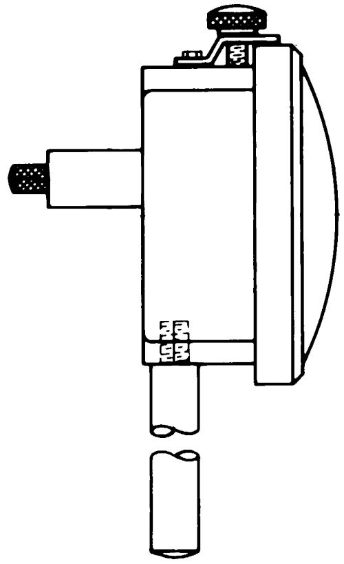
The typical configuration of a dial indicator features a sensitive contact in line with the face of the indicator. Typically, an upward movement of the contact represents a larger value on the face of the indicator.
With a perpendicular indicator, the sensitive contact is at a right angle to the face of the indicator, and an inward movement of the contact toward the face of the indicator represents a positive value.
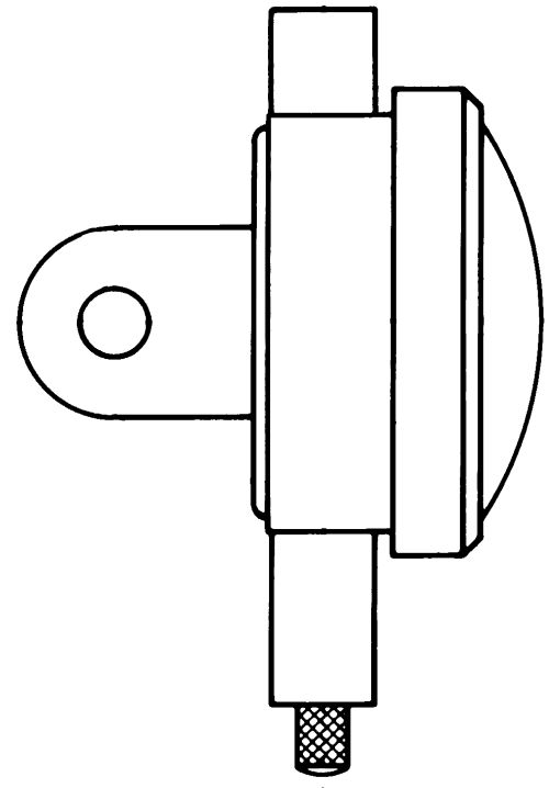
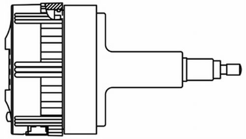
With the short range digital indicators commonly seen on comparative style gages, the transducer is a stand-alone item. It can be moved out of its standard case and mounted in a special back on the rear of the normal display. Thus, the indicator looks and acts like it always does, but the transducer is now perpendicular to the back in a very compact package.
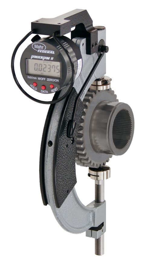
In the case of this gear gage, it was important to measure the part while still mounted in the machine. By applying a perpendicular digital comparator to the existing mounting, the operator can clearly see the size and make the appropriate decision.
Share


.png;maxWidth=45;format=webp)
DMG MORI - Cincinnati
Featured Content
View More


Takumi USA
Featured Content
View MoreOne final note: the April print issue marks the 20th anniversary of the Quality Gaging Tips column. That is perhaps not such a milestone in the greater scheme of things, but it has given me a very good perspective on the topic of dimensional gaging as a whole. While most of the things we talk about here are tactical, problem-solving matters, it is also clear that there are some larger trends driving the process. We’ll be discussing those in a special “Trends in Dimensional Gaging” feature in next month’s issue. I hope you check it out.


Read Next

Setting Up the Building Blocks for a Digital Factory
Woodward Inc. spent over a year developing an API to connect machines to its digital factory. Caron Engineering’s MiConnect has cut most of this process while also granting the shop greater access to machine information.
Read More
Registration Now Open for the Precision Machining Technology Show (PMTS) 2025
The precision machining industry’s premier event returns to Cleveland, OH, April 1-3.
Read More
Building Out a Foundation for Student Machinists
Autodesk and Haas have teamed up to produce an introductory course for students that covers the basics of CAD, CAM and CNC while providing them with a portfolio part.
Read More