Striking The Right Chord For Partial Diameters
Measuring the diameter of a hole is one of the most common inspection tasks in a production environment. Given the number and types of tolerances for diameters, many different gaging techniques are available to do these checks. From calipers to air gaging and everything in between, there is an appropriate gage for the application.
Share


Hwacheon Machinery America, Inc.
Featured Content
View More

Autodesk, Inc.
Featured Content
View More


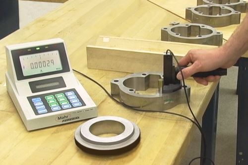
What if the hole you need to measure is not a complete circle? What if it’s a partial circle with less than 180 degrees of the arc available, or a combination of partial circles? For example, some hydraulic pump configurations incorporate holes (such as those depicted in the photo on the right) that cannot be measured with a conventional bore gage, as most bore gages measure strictly on the diameter.
The solution is to use a gage that measures chordal drop rather than diameter. I have written before about bench ID/OD gages that come in “T” and “V” plate configurations. In the “T” plate version, part diameter is read directly across the diameter.
However, the “V” plate design incorporates two reference stops—one at the top of each arm of the “V”—in addition to a sensitive contact. These reference contacts must be adjusted symmetrically to ensure that the part is staged on the center plane of the “V.” This double stop has a locating effect similar to that of a vee block and provides positive and precise location of the part on the gage. As a result, the gage does not directly measure diameter. It measures chord height, which is the distance between the sensitive contact and the chord formed by the two reference contacts.
In chordal measurements, the sensitive and reference contacts are not in a direct line, so there is not a one-to-one relationship between sensitive contact movement and the measurement diameter. Rather, the measurement is determined by a multiplier that varies with the angle between the reference and sensitive contacts, just like the multiplier used when measuring a diameter on a vee block. The angle chosen depends on the size of the hole, the portion available for measurement and the ease of using a multiplier to get the correct results.
Some chordal gages use an angle of 53 degrees that produces a requirement for a 4:5 ratio or a 1.25 multiplier to get the correct result. This means that for every four units of chord height measured by the gage, five units are shown by the indicator. This style of bench gage is used for small bearings or parts that can be brought to the gage.
Portable chordal gages are available for large, heavy pump housings. In these gages, two reference contacts, one on each side of the sensitive contact, set up the vee to make the chordal drop measurement. Often, the reference contacts span less than the partial arc available, so there is some room available to “explore” the measured diameter. Depending on the part size, the reference contacts can be set to various angles. This changes the multiplier needed to produce the correct result, but this is easily done with electronic readout devices.
Another thing to remember is that these configurations work only for comparative readings and cannot be stretched into the “absolute measurement” world. This is because there is a tight “window” of accuracy wrapped around the angle setup for the reference contacts. Moving the sensitive contact significantly away from or toward the reference contacts—as would normally happen in an absolute measurement scenario—changes the angle relationship. This changes the multiplier needed to get correct results. A scaling multiplier could be applied based on the measurement size and the location of the contact, but that’s pretty complicated for a bench fixture gage.
Fortunately, for most applications, the user need not worry about all these angles, ratios and chordal measurements. The gages take all the details into account. However, there are a number of things to keep in mind when using chordal gages:
• Make sure the measured parts are clean and free from oil/cooling fluid and debris.
• Make sure the gage is seated on both references: Most chordal gages have the two reference contacts plus a reference surface—almost like a stop collar—that sits on the face of the hole to square up the gage.
• Don’t force the gage when seating. Depending on the gage design, this can distort the reference contacts and influence the diameter reading.
• Master the gages with span masters to help verify operation and improve accuracy.
Read Next
5 Rules of Thumb for Buying CNC Machine Tools
Use these tips to carefully plan your machine tool purchases and to avoid regretting your decision later.
Read MoreRegistration Now Open for the Precision Machining Technology Show (PMTS) 2025
The precision machining industry’s premier event returns to Cleveland, OH, April 1-3.
Read MoreBuilding Out a Foundation for Student Machinists
Autodesk and Haas have teamed up to produce an introductory course for students that covers the basics of CAD, CAM and CNC while providing them with a portfolio part.
Read More


.png;maxWidth=150)


.jpg;maxWidth=300;quality=90)


