YCM Alliance
Published

Measurement System Analysis

Range, resolution and accuracy in digital amplifiers and inductive probes.

Share


There is no repeatable way to make a perfect part or a perfect measurement. So, the question becomes: “How imperfect is my measurement, and how can I make it less imperfect?” As imperfection—uncertainty—accumulates throughout the measurement process, it can be lessened by isolating specific causes and minimizing them. Overall, this process is known as “measurement system analysis.” We’ll start with range, resolution and accuracy in amplifiers and inductive probes and look at how they relate to SPC.
 
Digital dimensional bench amplifiers offer many great features, such as the ability to select the digital display resolution independent of the analog display range.
 
The advantage of this is that a measuring device, such as an inductive probe, with a large measuring range may be viewed at a fine, or high, resolution. This enables the operator to view an approach to a part more easily. It also enables measurement of a larger variation in part sizes.
 
The disadvantage is that high resolution does not mean high accuracy. The display resolution is often assumed to reflect the measuring system’s accuracy. For example, a probe might have a linearity error of 3.0 microns/120 microinches near the ends of its ±2 mm measuring range. The bench amplifier can display a digital resolution as fine as 0.01 micron/1.0 microinch (0.000001 inch). Thus, the danger! The probe may be able to achieve errors less than 0.25 micron/10 microinches, but it can do so only over a short measurement range near its null or electrical zero position, where it is most linear.
 
Most bench amplifiers help reduce this potential error. As a higher resolution is selected, the amount of visible measuring range is limited. This keeps the accuracy of the system more in-line with the higher-resolution readings.
 
Some amplifiers have two or more digital ranges. When using resolution settings of 0.1 micron/5 microinches, the digital display range is basically infinite and dependent on the available range of the inductive probe. When selecting a resolution of 0.01 micron/1.0 microinch, the digital range is limited to ±0.20 mm/±0.008 inch.
 
Limiting the range ensures that the user is aware of the type of measurement he or she is making. It makes no sense to measure at a 1-microinch resolution if the gage, fixture, environment, instrument and part cannot achieve sufficient accuracy to justify the high-resolution selection.
 
It makes no sense to have very high resolutions on relatively loose tolerances. All you tend to get is a lot of numbers, which adds operator confusion. A general rule for ease of use is to limit the digital resolution to no more than 1/40 of the total part tolerance. Some might think that it should be as little as 1/10 of the part tolerance, but this can limit the use of measurement data. This is especially true when collecting data for process control, as SPC analysis may require higher resolution to ensure enough variation.
 
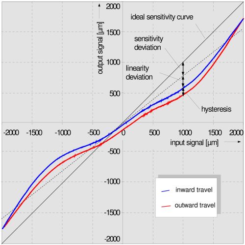
The basic identity of an inductive probe is its electrical signal output curve, which is characterized by the “S” shape shown in the graph on the right. The graph plots the deviation error from an ideal straight line over the entire measuring range of the probe. All inductive analog probes have increasing deviation, or linearity error, as the reading moves away from their null, or electrical zero position.
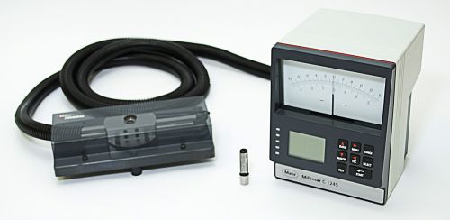
 Thus, these are called zero-, or center-based systems.
 
The “S”-shaped curve is a result of the mechanical movement as the spindle positions the core (mounted on spindle) up and down inside a coil assembly. The electrical signal of the coil is balanced at an electrical zero output when the core is precisely in the middle of the coil assembly. Slight inaccuracies tend to be at the extremes of the measuring range, so the curve becomes “S” shaped. This is why amplifier readouts allow the raw probe signal to be displayed in special absolute modes so the most accurate part of the probe can be set against a zero or nominal master. This type of measurement system is called a comparative system because it compares the difference between a part and its master. When set up correctly, accurate readings can be obtained.
 
Probe ranges are set by their mechanical design. Inductive probe resolution is limited by the amplifier design, display instrumentation and mechanical design. Electronically, an inductive probe’s resolution is infinite, but mechanically it is limited to repeatability and hysteresis characteristics. Thus, the first step in selecting the right probe for an application is the application itself.


YCM Alliance
OASIS Inspection Systems
EZ Access - Have it all with Ez - Mazak
The Automated Shop Conference
Universal Homepage Package W4900 Indicator
Koma Precision
DNS Financial Services America
Techspex
Gardner Business Intelligence
MMS Made in the USA
Hurco
BIMU 2024

Read Next

Sponsored

Increasing Productivity with Digitalization and AI

Job shops are implementing automation and digitalization into workflows to eliminate set up time and increase repeatability in production.

Read More

Encountering Surface Finishes in the Everyday World

Surface measurement is becoming increasingly important to ensure proper performance of a manufactured product. Advanced surface measurement tools are not only beneficial in the manufacturing industry but also have unconventional applications.

Read More
Turning Machines

A History of Precision: The Invention and Evolution of Swiss-Style Machining

In the late 1800s, a new technology — Swiss-type machines — emerged to serve Switzerland’s growing watchmaking industry. Today, Swiss-machined parts are ubiquitous, and there’s a good reason for that: No other machining technology can produce tiny, complex components more efficiently or at higher quality.

Read More
YCM Alliance