
Optical Micrometer Serves Bearing Maker as Alternative to CMM, Comparative Gaging
Over the decades, this bearing manufacturer has successfully created a variety of roller bearing products. However, with many products comes many part geometries that have to be measured with high precision. Optical micrometry has proven to be a precise solution.
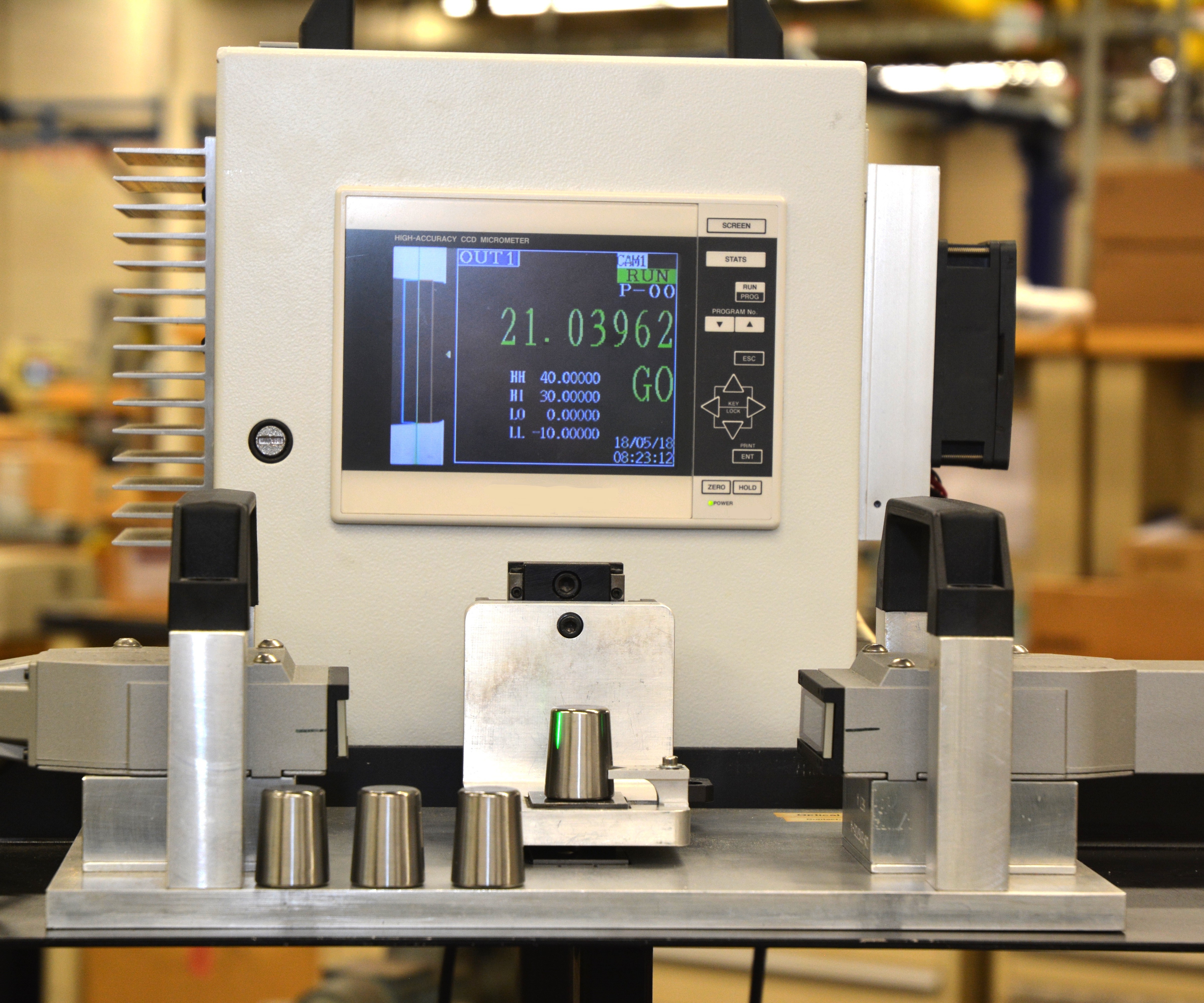
A thrubeam optical micrometer measures the diameter of Timken tapered rollers after being ground. The micrometer does not require part-specific mastering or part-specific workholding. It tolerates the shopfloor environment with only periodic cleaning of the exterior lens of the transmitter and receiver.
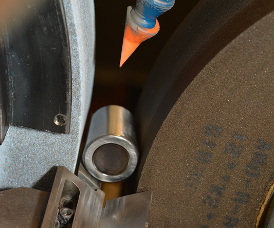
This example shows a Timken tapered roller after being ground. Located at the grinder, the optical micrometer provides immediate size feedback for precise control of the process.
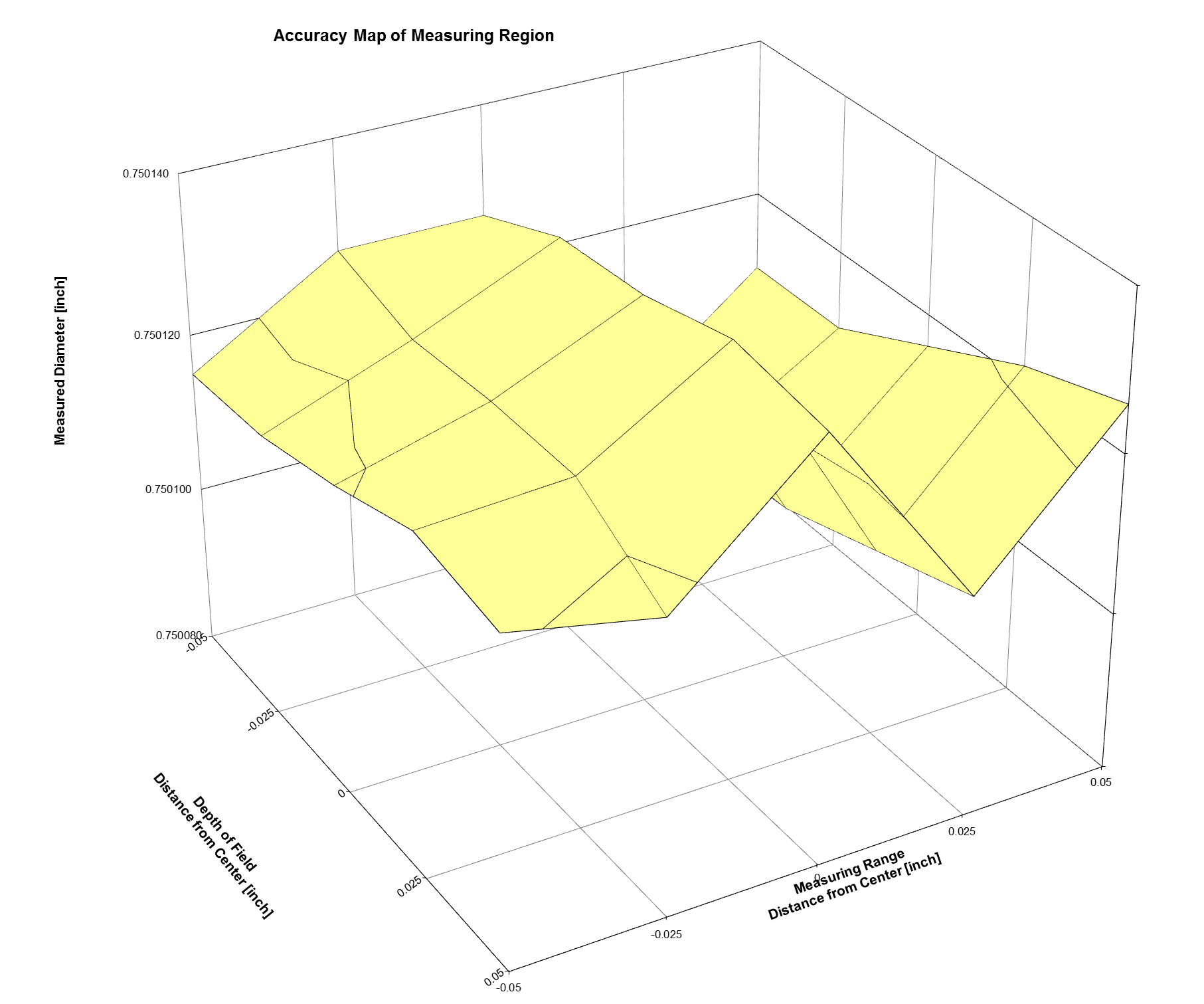
This is typical mapping of a measured diameter across the measuring region (measuring range versus depth of field) of an optical micrometer. If a certified gage pin is used, the map represents measured error across the measuring region. The error map can be used to improve the absolute accuracy of the optical micrometer.
Share


The humble bearing may just be one of the least-sung of unsung heroes. But bearings are important not only for manufacturers whose advanced equipment relies on them for smooth and reliable motion, but for too many machines (and their users) to number.
Bearings are also paramount to The Timken Co., headquartered in North Canton, Ohio. The company is a global leader in friction-management technologies and offers one of the most complete lines of anti-friction bearings in the industry. This longstanding success has led to a gaging challenge: The company manufactures a lot of different bearing series, amounting to thousands of different component geometries, each of which must be measured to extremely tight tolerances.


To better accommodate these needs, Timken has added optical metrology to its suite of tactile gaging technologies.
An Alternative to Comparative Gaging and CMMs
Comparative-contact gaging, set up to part-like masters, traditionally has been employed to measure the outer diameters (ODs) of axisymmetric components—components that are symmetrical along a given axis, like roller bearings. Comparative gaging is direct, simple to use and self-compensating for datums and temperature. However, precision masters are costly to manufacture and maintain. In addition, comparative gages tend to require series-specific tooling to fixture the parts for gaging.
As one alternative to comparative gaging, high-precision coordinate measuring machines (CMMs) have been used to measure these bearing components. As an absolute gage, CMMs do not require part-like masters and usually do not require series-specific tooling for measurement. However, factors such as maintenance, recertification and sequence programming can cause the initial capital cost and overall cost of ownership to trend high. Also, CMM measurement cycle times can be much longer than those of comparative gaging. Not only that, but some parts are susceptible to deformation, deflection or marking from the CMM probe tip contact force. These are unacceptable conditions for Timken, which requires the utmost precision and fast cycle times to stay competitive.
An alternative that addresses the shortcomings of both comparative gaging and CMMs is the optical micrometer. According to Larry Keller, metrology and gaging technologist with Timken, thrubeam optical micrometers are a very effective means of measuring the ODs of axisymmetric components. Optical micrometers—such as those made by Mitutoyo, Keyence and others—are absolute, permanently calibrated gages and do not require mastering. They can also be multipoint-calibrated to qualified gage pins of various diameters or calibrated to part-like masters. High measurement accuracy over a measurement range sufficiently large for many bearing components enables optical micrometers to successfully compete for roles in absolute OD measurement.
Adjusting to the Optical Micrometer’s Peculiar Sensitivities
The optical characteristics of the micrometer do vary across the measuring region. A certified gage pin mounted to an X-Y precision stage may be used to map the error in the measured diameter across the measuring region (that is, the measuring range versus depth of field). Once the optical micrometer is error-mapped and compensated for errors, Timken has found the gage type to be capable of meeting the company’s accuracy specifications.
Technically, diameter measurements can be obtained on a part located physically at multiple locations in the measurement region. However, the part axis has to be consistently located at a specified location in the measuring region in order to take advantage of the mapping, and this is how the micrometer delivers its most accurate results. In addition, the part axis must be optically aligned to the micrometer; that is, the part axis must be orthogonal to the direction of the micrometer scan. Misalignment in the direction of scan will not generally result in a significant error in the measured diameter at that cross section. However, for some part geometries (tapers or curvatures along the part’s length) and large skews, the measured diameter will not correspond to the true diameter of the part at that plane. Misalignment perpendicular to the direction of scan will more likely result in an error of the measured diameter at that cross section.
Mr. Keller explains how new users are trained to understand the new technology’s sensitivities in this area. In an exercise, a new user is asked to locate a 10-mm-diameter master part at multiple locations in the measuring region of an optical micrometer with 30-mm measuring range, he says. The distribution of measured diameters is recorded, and the distribution mean is compared to the true diameter. Then, that new user will measure the master part multiple times again using workholding registration that is integrated into the gage, which causes the part axis to be located at a specific desired location. In the latter case the distribution is much narrower and the distribution mean is much closer to the true mean. After this demonstration, workers who are new to the optical micrometer understand the importance of diligence and consistency in part axis location, he says.
The greatest concern Mr. Keller’s department had upon deployment of the micrometer has been part cleanliness. “Part cleanliness requirements for optical inspection are similar to the requirements for tactile inspection with a CMM. Because of smaller gaging forces, CMMs tolerate less contamination on the part surface than do comparative contact gaging,” he says. Optical micrometers, similarly, cannot tolerate any surface contamination at the measurement plane. As a result, Timken is deploying part cleaning ahead of optical measurement, much as it has done prior to CMM measurement.
Edge detection issues such as part surface contamination, surface texture and reflectivity restrictions, and edge dispersionc an remain problematic, Mr. Keller says. However, averaging several diameter measurements of the part rotated about its axis enables erroneous measurements to be detected and remeasured. Circumferential averaging also factors a part’s out-of-round variations into the composite diameter measurement.
Benefits Worth the Change
Having gotten used to the micrometer’s particular sensitivities and limitations, Mr. Keller says that the benefits are nevertheless multiple.
The optical micrometer has a high-frequency response, a small sensed area that is mandatory for tapered or curved parts, and a large standoff distance. Since there is no contact, there is no risk of part deformation, deflection or marking from a probe tip.
The optical micrometer has demonstrated good capability in formalized measurement system analysis testing when measuring bearing-component diameters. “It compares favorably to CMMs with 1-micron first-term volumetric accuracy specifications,” Mr. Keller says. Additionally, the system has acceptable environmental tolerance of factory oil and dust and of temperature and humidity swings. It also costs less than the other gaging approaches discussed above (either comparative or absolute), both in terms of overhead and cycle times.


Related Content

6 Machine Shop Essentials to Stay Competitive
If you want to streamline production and be competitive in the industry, you will need far more than a standard three-axis CNC mill or two-axis CNC lathe and a few measuring tools.
Read More
Help Operators Understand Sizing Adjustments
Even when CNCs are equipped with automatic post-process gaging systems, there are always a few important adjustments that must be done manually. Don’t take operators understanding these adjustments for granted.
Read More
How to Calibrate Gages and Certify Calibration Programs
Tips for establishing and maintaining a regular gage calibration program.
Read More
4 Ways to Establish Machine Accuracy
Understanding all the things that contribute to a machine’s full potential accuracy will inform what to prioritize when fine-tuning the machine.
Read MoreRead Next

Inside Machineosaurus: Unique Job Shop with Dinosaur-Named CNC Machines, Four-Day Workweek & High-Precision Machining
Take a tour of Machineosaurus, a Massachusetts machine shop where every CNC machine is named after a dinosaur!
Read More
IMTS 2024: Trends & Takeaways From the Modern Machine Shop Editorial Team
The Modern Machine Shop editorial team highlights their takeaways from IMTS 2024 in a video recap.
Read More
The Future of High Feed Milling in Modern Manufacturing
Achieve higher metal removal rates and enhanced predictability with ISCAR’s advanced high-feed milling tools — optimized for today’s competitive global market.
Read More