How to Slash 5-Axis Finishing Time
Sponsored ContentFinally there is an alternative to ballnose endmills for finishing 3D parts. The combination of finishing tools shaped to provide more cutting surface and a CAM system with the ability to apply them on a five-axis machining center can dramatically reduce finishing cycle times while delivering better surface finishes.
Share
Using a tool shaped more like the surface it is finishing reduces cycle time and improves finish.
Much has been made of newer roughing strategies such as high efficiency milling and for good reason. This process can improve metal removal rates by as much as 70 percent yet still improve tool life. But what about finishing? For contoured 3D parts such as dies, molds, orthopedic implants, turbine blades and some aerospace parts, finishing can account for the largest portion of cycle time, and sometimes by a lot. It’s also the most important process because it will determine accuracy and the quality of the surface finish which in turn impacts the need for post machining processes such as EDM and mechanical or hand finishing.
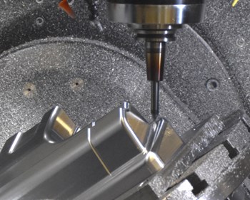
Finishing with a taper form cutter
When finish machining with ballnose endmills the main tradeoff has always been surface finish vs. cycle time. The need for smooth surface finish on many features often requires small diameter tools with tiny stepovers and traditionally consumes the majority of machining time. Larger diameter tools speed the process by naturally leaving wider and shallower surfaces between cusps. But the size of that cutting diameter is restricted by the nature of a cylindrical ballnose endmill, so extremely large cutting diameter tools are impractical or impossible. But thanks to the development of finishing tools that are shaped to present extremely large cutting areas with the side of the tool, rather than from only the tip, finishing cycle times can be dramatically reduced while still generating better surface finishes and blends from one surface to another.
Yet having better tools is only half of the equation. The other half is being able to easily generate toolpaths that fully realize the potential that these tools offer. Well known CAM developer Mastercam has been doing just that with the development of its Accelerated Finishing capability in partnership with leading cutting tool manufacturers such as Emuge which has a line of formed profile finishing tools they call Circle Segment Cutters. Here’s more on what these tools can do and how to apply them.
Generating Smaller Cusps with Fewer Passes
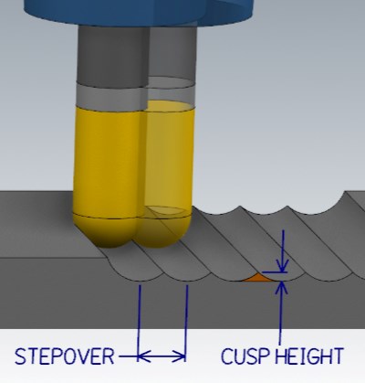
The only way to get a smoother surface finish with a conventional ballnose endmill is to reduce the stepover to lower the cusp height.
Anyone who does 3D machining with ball mills knows the tradeoff. Getting the smoothest surface means keeping the cusp height between tool passes as small as possible. Using a large diameter tool helps, but you still must use very small stepovers or stepdowns to generate fine surface finishes, which results in extremely long cycle times and huge part programs. It only gets worse on features where a big tool won’t fit, and you are forced to use very small edge radius tools with even smaller stepovers. Moreover, especially in 5-axis machining, small tools increase the risk of toolholder collisions with the other features of the workpiece or fixture.
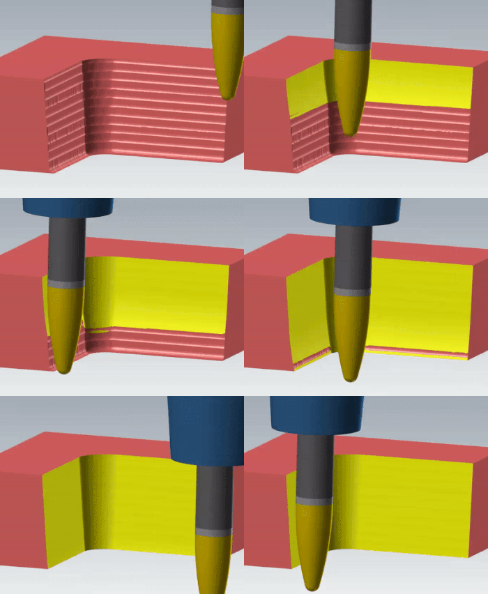
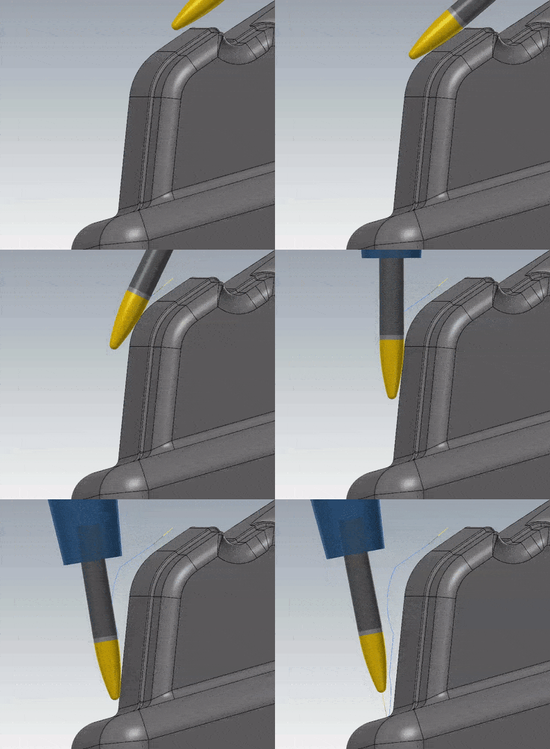
In this animation the lines represent what the stepdown might be with a very large ballnose endmill. With the oval shaped cutter the surface can be machined with far fewer passes without increasing cusp height.
Circle Segment finishing tools, and similar tools such as barrel cutters, can dramatically mitigate these limitations. For example, this oval form cutter has a large radius contour on the side of the tool that better fits a sloping workpiece surface, yet also has a small radius form at the point which can reach fine features such as the bottom edges of a pocket. This tool essentially combines an otherwise impossibly large diameter ball mill and small radius cutter in a single tool. It allows the slope to be cut with much larger stepdowns, yet still reduce cusp height for a better finish.
The ability to generate cuts like this unlocks the true potential of a five-axis machining center to more efficiently generate smooth surface finishes on contoured forms. And these tools can also be used on 3-axis machines to more efficiently cut some sloped features such as the draft angle on a mold cavity.
Here’s how a different form cutter form looks on a real 5-axis machine:
Five-axis Accelerating Finishing
Case in Point
This B-pillar punch application shows how Accelerated Finishing can reduce cycle time. The punch is a tool that is used to form the roof support structures located between the windows of a car. The material is 6061-T6 aluminum, 81% of which will be removed from a block about 22” x 7” x 6” in size. The overall cycle time to finish this tool using conventional milling methods is nearly 18 hours.

Surface segments where Accelerated Finishing was applied are shown in red. Green segments used a conventional finishing process with a 0.250” ballnose endmill.
While Accelerated Finishing couldn’t be used on the entire part, it could be applied to about 60% of the 215.6 square inches of the total surface, shown in red. With the traditional finish portion (40% of surface) a 0.250” ball mill was used at 10,000 RPM with a 60 IPM federate and stepovers of 0.003”. The operation took 10 hours and 58 minutes.
This video shows Accelerating Finishing dramatically reduced cycle time on this automotive pillar punch.
For the Accelerated Finishing portion, a 12mm Emuge Taper Form endmill was used at 10,000 RPM, an 80 IPM feedrate and 0.05” stepovers. With this process 60% of the surface area was finished in just 1 hour and 12 minutes.
The comparative finishing rates were 7.91 in2 per hour with conventional finishing vs. 128 in2 per hour with Accelerated Finishing.
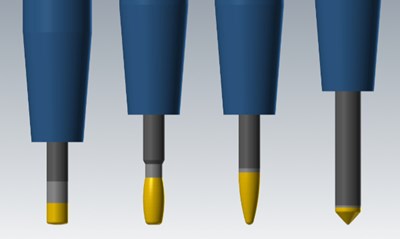
Examples of circle tool shapes (l-r):lens shape, barrel, oval form, and taper form.
Efficiently Creating Efficient Toolpaths
Circle profile cutters come in a variety of shapes and sizes, which can present a programming challenge with a CAM system only equipped to handle standard tool sizes and configurations. These tool profiles include lens shape, barrel, oval form, taper form and others. Using them effectively requires tool paths that keep the tool’s cutting profile engaged with the surface of the part at a precise angle proper for that tool design.
Mastercam has made this easier first by incorporating a variety of these profile tools into its tooling library with the full tool geometry already stored. It includes the entire Emuge line of Circle Segment Cutters as well as a growing list of tools from other manufacturers. New tool profiles can also be created with an easy-to use-parametric dialog form that describes new tool profiles with relatively few input values.

Left image shows surfaces where Accelerated Finishing could be used on this sorting slider. Right side shows the most efficient toolpath for a lens form cutter.
The software can control three cutting edge radii on one tool simultaneously and then drive that tool across multiple surface segments in a single continuous toolpath to create a smooth, accurate and efficient cutting action
While you won’t be able to use Accelerated Finishing on every feature of a complex 3D part, as the video above shows the benefits are substantial in the cases where it applies. The best applications are contoured surfaces that cover a larger, relatively open area of the part. This might mean machining the bottom of a mold cavity with a lens tool or machining the sides of a mold core with a taper or oval tool. In either case, a finishing operation that might have taken several hours with a ballnose endmill could be reduced to less than an hour with the strategic application of various circle-segment cutters. And you can get a smoother surface in the bargain.
Please go to Mastercam.com to get more information on Accelerated Finishing Technology.
