Hold The Tool On Target
Toolholders deliver tight concentricity - no tramming required.
Share


.png;maxWidth=45)
DMG MORI - Cincinnati
Featured Content
View MoreWhen the tool is off-center in a machining center spindle, the flutes don't share the work. With each revolution, the cutting edge farthest from the axis of rotation tries to take a deeper bite than the other edges. This can lead to dimensional error and poor surface quality, as well as reduced tool life as the hardest-working flute sees more than its share of wear.
Collet toolholders offer a proven solution. The collet is essentially a spring wrapped around the tool's shank. Pressing the tool from every direction toward the center line, the collet can effectively neutralize runout. And when this action alone doesn't provide enough centering, there is a simple method for improving concentricity. It involves an indicator and a mallet. The machinist measures the tool's runout in the toolholder—either in the spindle or out of it—then taps the high spot, and repeats both steps until the runout is appropriate to the cut.
A skilled machinist using this approach can achieve any level of tool concentricity that a precision cut may require. Tighter concentricity simply requires a more sensitive indicator. And more patience and finesse. And time.
But there are alternatives. Where purely mechanical toolholders may fail to achieve precise concentricity without manual intervention, at least two technologies—hydraulic and shrink-fit toolholders—can center the tool more repeatably.
Through the mechanisms of hydraulic pressure and thermal contraction, respectively, these toolholders close by essentially the same amount all the way around the shank of the tool.
Thus they take the principle of the collet toolholder one step further. An ideal collet also would collapse by the same amount all the way around the tool. However, within a real-life collet that has, say, 1/64 inch of play in the ID before closing, tightening the nut may compress this play disproportionately to one side of the tool. If the resulting runout is too high for the cut, then it takes an indicator to diagnose this and a mallet to correct it.
By contrast, both hydraulic and shrink-fit toolholders essentially automate the tool centering process. By closing the toolholder ID uniformly, both permit "hands off" tool centering—no tramming or tapping required.
Hydraulic Toolholding
Robert Laube, manufacturing manager for Hydra-Lock Corporation (Warren, Michigan), points to a Windsor, Ontario, automotive plant to illustrate the potential tool life gains that can come from centering the tool.
The plant adopted his company's hydraulic toolholders to machine spool bores for valve bodies in 380 aluminum. Tool life for this operation had been 10,000 to 12,000 passes. However, after incorporating hydraulic toolholders to achieve consistent tool centering, the plant extended tool life to 80,000 passes. "And even at this point," says Mr. Laube, "the tools were still in the category, `sharp.'"
The idea that led first to hydraulic workholding for lathes, and from there to hydraulic toolholding, came when an engineer observed a "flaw" in a hydraulic cylinder. The cylinder wall, he observed, expanded when pressure was applied.
A hydraulic toolholder turns this phenomenon inside-out. Inside the toolholder, surrounding the hole for the tool shank, is an expanding steel sleeve filled with oil. Turning an actuating screw in the side of the toolholder increases the pressure on this fluid to as high as 15 tons per square inch when the screw is bottomed out. The rising pressure causes the walls of the sleeve to bulge, thereby closing the ID and solidly clamping the tool.
Mr. Laube says this effect produces the most effective mechanism for centering a tool. Tool concentricity on his company's hydraulic toolholders repeats to within 50 millionths of an inch TIR (total indicator reading), he says.
The metal of the sleeve expands only within its elastic limit, so it relaxes back to its original dimensions when the pressure is released. Typical clearance for the "open" sleeve is 0.005 inch for a 1-inch diameter tool, plus 0.002 inch for each additional inch of diameter.
Significant demand for hydraulic toolholders began in the late 1980s, says Mr. Laube—a result of the need for precision machining at faster and faster spindle speeds. Hydraulic toolholders minimize vibration for improved performance at these high speeds. Mr. Laube sees two reasons for this.
One reason relates to the hydraulic fluid itself. The toolholder's oil reservoir, he says, "acts as a natural damping agent and impact cushion," reducing vibration not just from unbalance, but from any number of sources.
But the other reason for the hydraulic toolholder's smooth performance at high speeds is simply the balance that comes from improved centering. Separately, a tool and toolholder both may be balanced, but when the toolholder is hydraulic, the combination also is balanced when the two are brought together.
A hydraulic toolholder can be chucked and unchucked with no significant change in the balance, Mr. Laube says. However, "in designs using a collet and locking nut, just loosening and retightening the nut will change the balance condition by up to 30 gram-millimeters."
Still, a tool centered in the toolholder may not be quite so centered when the toolholder goes into the spindle. Mr. Laube says special "adjustable TIR" toolholders address this problem. A screw that controls the position of the tool/toolholder center line can bring the tool in-line with the spindle's axis of rotation. On a spindle with a worn location taper, this feature can let the operator fine-tune the toolholder for that particular spindle just one time. Provided the toolholder is kept at this setting, its hydraulic clamping can be trusted to locate the tool on the same spindle's center line each time a new tool is loaded.
Shrink-Fit
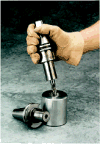
The metal of a shrink-fit toolholder "relaxes" in the opposite direction from a hydraulic. The shrink-fit toolholder is heated to where its ID is open enough for the tool to be inserted. It then cools toward the original, "closed" condition.
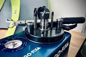
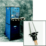
A shrink-fit toolholder's ID is deliberately undersized. For example, a 0.5-inch-diameter tool fits a shrink-fit toolholder diameter of 0.4985 inch (according to a physics formula). Thermal expansion opens the toolholder the rest of the way, after the toolholder is heated in a stand-alone induction heater. Cooling creates the clamp, as the contracting metal pulls in around the tool.
George Taylor, sales manager for Tooling Innovations (Bad Axe, Michigan), describes the resulting union as "essentially an integral shank tool." The shrinking ID creates a clamp force upwards of 10,000 pounds—compared to about 6,000 pounds for the typical spindle drawbar that will hold the toolholder in place.
Concentricity falls within 0.0002-inch TIR. However, the virtue of shrink-fit, says Mr. Taylor, is its ability to deliver this concentricity along with high rigidity—something a collet toolholder, for example, often can't do.
"With a collet toolholder, you could achieve the same concentricity that you could with a shrink-fit system," he says. However, not only would this take time—for the many iterations of checking and tapping the tool—but it would also leave two points of play to compromise the rigidity of the process when the tool is loaded in the spindle. There would be play between the toolholder and the spindle taper, and play between the collet and the toolholder ID.
As a result, the precisely centered tool could be used for drilling or reaming, he says, but probably not milling. A mill centered in a collet is unlikely to stay centered once it enters the cut.
By contrast, shrink-fit is the only toolholder system that leaves just one point of play—that within the spindle taper. Where the tool meets the toolholder, there is no "give," because the contracting metal closes with the same force upon the full contact area of the tool shank.
This makes shrink-fit appropriate for any rotary tool operation—drilling, reaming, boring, and even milling with relatively deep cuts.
The shrink-fit induction heating cycle for the toolholder takes about 30 seconds total. This includes cooling time, during which the toolholder and cutting tool are placed on an aluminum cooling block (by an operator wearing gloves) to speed heat dissipation. To remove the tool, the toolholder is simply re-heated.
The process doesn't shorten the life of the toolholders, Mr. Taylor says. An aerospace manufacturer recently confirmed this by clamping and unclamping a shrink-fit toolholder 5,000 times. This manufacturer decided to commit to the shrink-fit system after the test produced no measurable toolholder deformation.
Shrink-fit toolholders themselves may be less expensive than comparable hydraulic toolholders or milling chucks, but given the added cost of the heating unit, the system still requires a significant initial investment. Payback can come from a number of sources, Mr. Taylor says.
The shrink-fit toolholder, like a hydraulic one, allows a shop to realize the benefits of efficient tool centering. Tool life can increase, and surface finish and precision may improve—all without the time and expense of manually centering the tool.
However, Mr. Taylor says shrink-fit can add one more source of payback to this list: shorter cycle time. With another toolholder design, tool chatter may place an artificial speed limit on the process, forcing the shop to accept a feed rate lower than it might otherwise achieve. But the rigidity of the shrink-fit toolholder's grip on the tool can let the process break through this limit—provided, that is, that the toolholder is indeed the weak link.
"The fixturing strength has to be there, too," says Mr. Taylor. "A shop can upgrade the process to more rigid toolholding, only to find that now it's the fixture that's prone to chatter."
But add rigid toolholding when the rest of the process is also rigid, he says, and feed rate can go much higher—perhaps to the machine's limit—without compromising the quality of the cut.
Related Content
PowRgrip Responds to Three Tooling Trends
Rego-Fix’s PowRgrip tooling system has expanded over the past 20 years to incorporate a wider range of tool sizes, as well as automation.
Read MoreLyndex-Nikken Toolholders Offer Stable, Versatile Machining
Polygonal shank toolholders provide a rigid connection between the tool and machine — ideal for all processes both in turning and milling.
Read MoreMaking the Most of Mixed Toolholder Assemblies
While nearly all ER systems will have cross compatibility, they’ll have small differences across manufacturers that make their implementation at the shop level not as standard.
Read MoreHow to Mitigate Chatter to Boost Machining Rates
There are usually better solutions to chatter than just reducing the feed rate. Through vibration analysis, the chatter problem can be solved, enabling much higher metal removal rates, better quality and longer tool life.
Read MoreRead Next
Registration Now Open for the Precision Machining Technology Show (PMTS) 2025
The precision machining industry’s premier event returns to Cleveland, OH, April 1-3.
Read MoreBuilding Out a Foundation for Student Machinists
Autodesk and Haas have teamed up to produce an introductory course for students that covers the basics of CAD, CAM and CNC while providing them with a portfolio part.
Read More5 Rules of Thumb for Buying CNC Machine Tools
Use these tips to carefully plan your machine tool purchases and to avoid regretting your decision later.
Read More.png;maxWidth=970;quality=90)


.png;maxWidth=150)





.png;maxWidth=300;quality=90)

.jpg;maxWidth=300;quality=90)


