
Machining is More Than Geometry
While CAD/CAM software may represent machining operations as geometry, you must consider vibration effects to obtain a successful outcome.


The introduction of CNC for machining centers enabled a digital approach, where the desired part is defined by a solid model produced using CAD software. The CNC tool paths used to machine this part are then generated using CAM software. While this is a key capability with continued advancements, a singular focus on geometry neglects key physical considerations that must be addressed for cost-effective and reliable manufacturing performance. This article focuses on the effect of vibration during the milling process and its influence on part quality.
For discrete part manufacturing by milling, the digital world steps are:


- Design the part using CAD software
- Select the cutting tools that will be used to remove material from the preform (bar stock, forging, casting or additively manufactured near-net shape part)
- Generate the tool paths using CAM software to produce the final design from the preform based on the CAD part representation
- Remove material by following the tool paths to obtain the desired geometry.
These steps suggest that a digital world treatment is sufficient, but we live in a physical world. What can go wrong? The tool may not follow the commanded path. This is due to machine tool positioning errors, which may be slowly varying (quasi-static errors due to the machine kinematics or its thermal state) or dynamic in nature (observed in high-speed contouring, for example).
The tool may wear out. Tool wear occurs because machining is a competition between the sharp cutting edge and workpiece. Higher speeds lead to higher temperatures and accelerated wear, in general. The wear rate depends on the tool material/geometry, work material, coolant application and parameters.
Vibration may be excessive. The cutting force causes tool and workpiece displacements, which can result in chatter, a self-excited vibration. The behavior depends on setup, including the tool tip frequency response function that describes the tool-toolholder-spindle-machine dynamics.
Let’s consider the vibration implications. Cutting tools are designed to be stiff. The materials are selected to be hard and resist deformation. However, when the cutting force is applied to the tool, it still deflects. You can think of a tool as a stiff spring. Sometimes the workpiece is also flexible. In this case, the workpiece can deflect as much or more than the tool when the cutting force is applied. It can also be thought of as a spring.
The cutting force is generated as the tool shears away material in the form of a chip. The cutting force depends on the chip thickness (which depends on the feed per tooth and tooth angle in the cut), chip width (the axial depth in milling), material properties and tool geometry. Larger chip width and thickness values give higher force.
If a force is applied to a spring, it deflects, but why does vibration occur in milling?
- The endmill teeth constantly enter and exit the cut
- The cutting force varies with these entries and exits
- The variable cutting force acts on the flexible tool and/or workpiece and causes displacement that varies with time. This variable displacement is vibration.
Because the cutting force depends on the chip thickness and the chip thickness depends on the vibration of the current tooth as it removes material as well as the surface left behind by the previous tooth, chatter (self-excited vibration) can occur in milling. Chatter produces large forces and vibration, poor surface finish and potential damage to the tool, spindle and part. However, if the tool tip frequency response function is measured, a stability map can be constructed to identify spindle speed-axial depth combinations that provide stable machining conditions, as well as those that produce chatter.
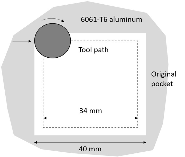
Figure 1: Pocketing tool path. Source: Tony Schmitz
This stability map depends on the radial depth of cut from the tool path. This is the reason you may have observed stable cutting most of the time in a pocketing routine, but you heard chatter (a characteristic squeak) in the corners. Figure 1 depicts a spiral-out tool path, where the radial immersion increases from 25% along the wall to 75% in the corner. The milling parameters are: 25% radial immersion up milling (3-mm radial depth), 12-mm-diameter end mill with four teeth and a 30-degree helix, 4-mm axial depth, 0.2-mm feed per tooth and 6,400-rpm spindle speed.
The stability maps for the 25% and 75% radial immersion conditions are shown in Figure 2. Spindle speed-axial depth combinations above the blue stability boundary are unstable (exhibit chatter), while those below the boundary are stable. We see that the 6,400-rpm spindle speed and 4-mm axial depth combination is stable for 25% radial immersion (left), but is unstable for 75% radial immersion (right).
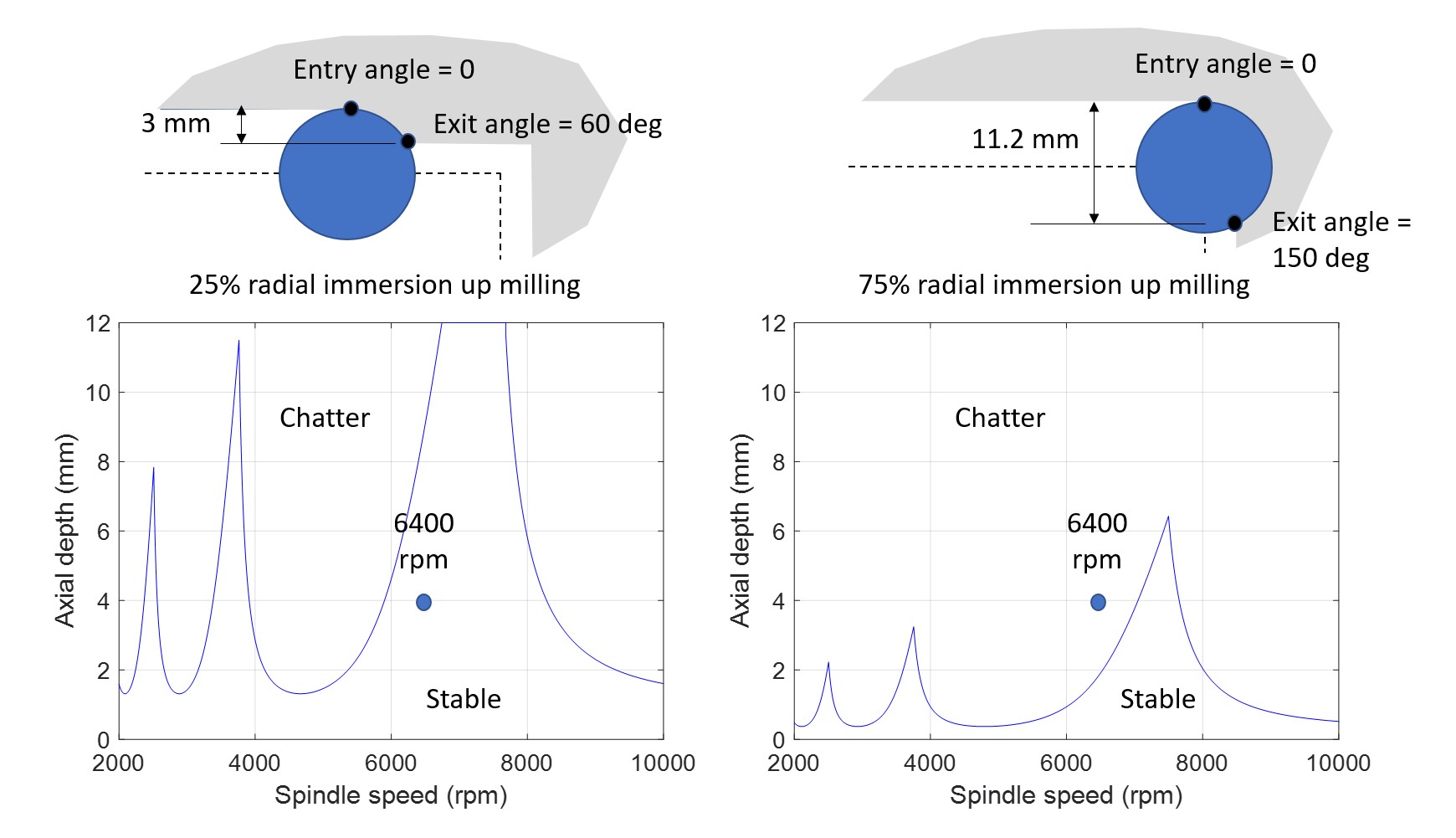
Figure 2: Stability maps for 25% radial immersion (left) and 75% radial immersion (right).
Source: Tony Schmitz
This example highlights the importance of considering vibration effects when selecting CAM milling parameters. Given a stability map at the process planning stage, the trial-and-error steps that are sometimes required to finalize tool paths can be minimized.


Read Next

Obscure CNC Features That Can Help (or Hurt) You
You cannot begin to take advantage of an available feature if you do not know it exists. Conversely, you will not know how to avoid CNC features that may be detrimental to your process.
Read More
The Cut Scene: The Finer Details of Large-Format Machining
Small details and features can have an outsized impact on large parts, such as Barbco’s collapsible utility drill head.
Read More
3 Mistakes That Cause CNC Programs to Fail
Despite enhancements to manufacturing technology, there are still issues today that can cause programs to fail. These failures can cause lost time, scrapped parts, damaged machines and even injured operators.
Read More