
Continuous Turning On Turn-Mills
A new CAM feature continuously manages B-axis head rotation to allow turn-mills to completely turn inner and outer workpiece profiles using a single tool.
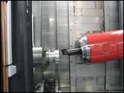
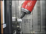
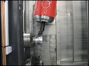
The B-axis contouring cycle allows one tool to turn an entire profile in a single operation. The range of B-axis motion during turning is controlled by the total allowable B-axis head rotation and proper tool lead angle.
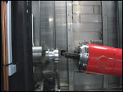
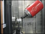
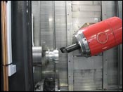
During this B-axis contouring turning operation, a single tool rotates to reach areas that would normally require a separate operation. Simultaneously, analysis of the part geometry and the cutting tool detects and prevents collisions.


A clear attraction to the turn-mill platform is the possibility to completely machine workpieces in a single setup. Advancements in CAM software now allow turn-mill machines equipped with a B-axis milling head to perform finish turning of inner and outer workpiece profiles using a single cutting tool. This new lathe finishing cycle can cut continuously along inner and outer profiles in one step with just one tool, eliminating the need to use a series of turning tools with different geometries.
The B-axis contouring cycle was developed by DP Technology (Camarillo, California) and is available in the company’s Esprit 2008 CAM package. The cycle takes an efficient approach by continuously rotating the B-axis as the cutting tool follows the contour, allowing the tool to reach areas that would otherwise be inaccessible due to the tool’s geometry. Using this new machining cycle reduces the number of cutting tools required, the number of tool changes and programming time while delivering a smooth, step-less surface finish. Ultimately, the possible results are saved time and money for machine shops.


Following The Contour
In June 2007, a successful B-axis contouring test cut was performed at Mori Seiki’s technical center in Los Angeles, California on an NT3150 turn-mill machine. The coordinates in the NC code were output for the tool nose center using the rotate tool center point (RTCP) function of the machine’s Fanuc control. The RTCP function, which must be used for the contouring cycle, makes the tool rotate about its control point rather than rotating about the B-axis pivot point.
The B-axis contouring cycle is based on Esprit’s SolidTurn contouring cycle. The major difference is the B-axis technology offers full control over the choice of B-axis rotation strategies and allowable B-axis angle limits.
Users can adopt two strategies to manage tool orientation throughout the turning operation. The first is to maintain a constant lead angle between the tool and the workpiece surface. Thus, the tool maintains the initial lead angle in relation to the profile being cut. This initial lead angle is a function of the original tool orientation in the B-axis head and the orientation of the first element in the profile. As the slope of the profile changes, the B-axis head tilts the tool accordingly to maintain the same lead angle relative to the workpiece surface. The total tilt of the tool is limited by a user-defined range of lead angles in addition to the software’s automatic part/tool collision detection capability. This strategy produces the best cutting conditions by keeping the optimal angle between the tool and the surface being cut. It does, however, require almost constant movement in the B axis, which can generate over-travel motion.
The second B-axis rotation strategy is to minimize tool rotation by tilting the tool only when necessary. This strategy maintains the initial tool orientation until the tool reaches a surface that cannot be cut with the tool is in its current orientation. Only then does the tool tilt as much as necessary to cut the surface within the user-defined B-axis angle limits. This strategy, used in the test cut mentioned previously, limits the rotation of the B-axis to areas that cannot be cut at a traditional tool angle.
Both strategies are easily verified and users can display tool-axis vectors on screen to determine the best strategy for a given part geometry. The user has full control over the range of B-axis rotation during the entire cut. One way to limit the angle of the tool is to limit total allowable B-axis rotation by applying user-defined minimum and maximum B-axis angles. Alternately, for even tighter control, user-defined minimum and maximum lead angles define the allowable range of the local lead angle of the tool.
Collision Prevention
Built-in collision detection prevents a collision between the part and the tool when the tool path is calculated. Instead of relying solely on the defined tool geometry, collision detection uses a silhouette of the tool that can be modified by the user. The shape of the tool silhouette depends on the actual tool geometry and user-defined clearance values for the front and back of the tool. Extra clearance can be added around the tool to avoid the possibility of the tool gouging the material as it cuts profiles that have a similar angle to the front or back of the tool.
Programmers no longer need to create several programs using traditional methods. Instead, a single B-axis contouring operation will finish an entire profile without stopping for tool changes. Eliminating tool changes saves precious seconds in the overall cycle time and also eliminates the possibility of witness marks where one tool finishes and another begins.
About the author: Ann Mazakas is manager of technical communications at DP Technology.


Related Content

5 Reasons Why Machine Shop Ownership Is Changing
Mergers, acquisitions and other ownership changes are an effect of Boomer-age shop owners retiring, but only in part. Also important: The way we think about machining has changed.
Read More
Tips for Designing CNC Programs That Help Operators
The way a G-code program is formatted directly affects the productivity of the CNC people who use them. Design CNC programs that make CNC setup people and operators’ jobs easier.
Read More
6 Steps to Take Before Creating a CNC Program
Any time saved by skipping preparation for programming can be easily lost when the program makes it to the machine. Follow these steps to ensure success.
Read More
5 Tips for Running a Profitable Aerospace Shop
Aerospace machining is a demanding and competitive sector of manufacturing, but this shop demonstrates five ways to find aerospace success.
Read MoreRead Next

The Cut Scene: The Finer Details of Large-Format Machining
Small details and features can have an outsized impact on large parts, such as Barbco’s collapsible utility drill head.
Read More
Obscure CNC Features That Can Help (or Hurt) You
You cannot begin to take advantage of an available feature if you do not know it exists. Conversely, you will not know how to avoid CNC features that may be detrimental to your process.
Read More
3 Mistakes That Cause CNC Programs to Fail
Despite enhancements to manufacturing technology, there are still issues today that can cause programs to fail. These failures can cause lost time, scrapped parts, damaged machines and even injured operators.
Read More