
Simulation Software Saves Time, Boosts Confidence
Vericut simulation software from CGTech provides the confidence the company needs to machine high-value parts without the time required for manual prove-outs or the risks associated with less-robust alternatives.
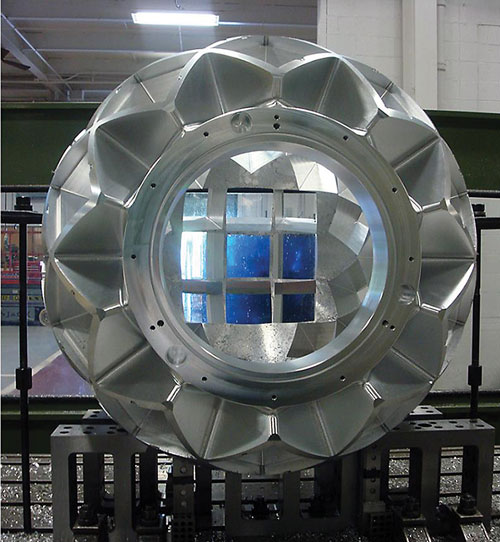
The diffractometer component required machining 51 square, tapered pockets, all of which point directly at the center of the sphere and require critical seal surfaces at precise locations. In addition to accurately machining these features, maintaining cutter clearance was a critical concern because the part was almost too big for the machine.
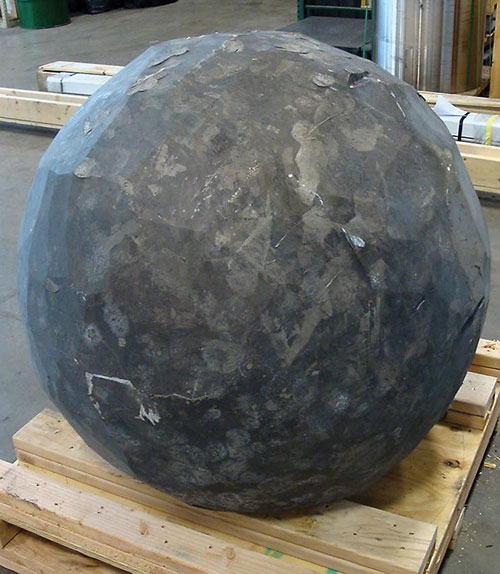
The diffractometer component began as a spherical, forged piece of aluminum that weighed 3,000 pounds.
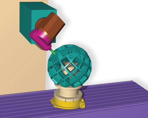
The first design for the diffractometer component’s custom, pedestal fixture would have mounted the part too close to the table, says Steve Ziff, CAD/CAM engineer at Keller Technology. Finding the correct height was a matter of making alterations to the fixture in Solidworks CAD software, importing the model into Vericut to see if it would work, and repeating that process until the design could be finalized.
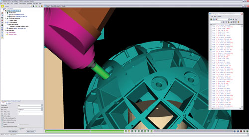
According to developer CGTech, Vericut simulation is based on the same post-processed G code used by machine tool controls. As opposed to verification systems that simulate only the tool’s interaction with the part, this ensures that all programmed moves are accounted for during first-part prove-outs.


The large, spherical part in the picture below might look like a daunting machining project, but for Keller Technology, this sort of work is common—high-value, custom jobs that typically involve low production quantities, complex geometries, no room for error and no second chances. For jobs like this, proving out machining processes before tools meet metal is critical, although that doesn’t diminish the importance of timely deliveries. Steve Ziff, CAD/CAM manufacturing engineer, says one particular system is critical to meeting both of these potentially conflicting goals: Vericut simulation software from CGTech (Irvine, California). Since installation a few years ago, the software has eliminated the need for time-consuming manual prove-outs, improved confidence on the shop floor and enabled faster setups.
little more than 1 meter in diameter and weighing more than 3,000 pounds. Machined on an SL 100 five-axis machine from Parpas America (Bloomfield Hills, Michigan), the part required removing more than a ton of material to bring it to its final weight to 610 pounds. Like much of Keller Technology’s work, the part was a one-off requiring high precision, custom tooling and relatively lengthy machining routines, and it had to be done right the first time—welding to fix any gouges was not an option.
problem, Mr. Ziff ex-plains, is that the shop’s CAM-integrated verification capability is limited to checking only the internal CAM file. As a result, the system evaluates only the cutting tool’s interaction with the part without accounting for other factors that affect the process. “In the real world, you’ve got a lot more things to worry about—doors, clamps, angle plates, how the part fits on the table,” Mr. Ziff explains. “There was no representation of the full machining environment.”
the context for simulations that run from the same post-processed G code used by machine tool controls. As opposed to CAM-integrated systems that are limited to only the internal CAM file, this ensures a more comprehensive rendering of how the process will proceed on the shop floor. “What Vericut does differently is that it puts the code itself in the driver’s seat,” Mr. Ziff says.


Related Content

How to Mitigate Chatter to Boost Machining Rates
There are usually better solutions to chatter than just reducing the feed rate. Through vibration analysis, the chatter problem can be solved, enabling much higher metal removal rates, better quality and longer tool life.
Read More
Improving Workflows in Small Shops with Custom ERP
Small shops might not be ready for all of the functionality of an off-the-shelf ERP system, but modular, custom ERP programs can help improve workflow while providing the flexibility to change as shops grow.
Read More
Tips for Designing CNC Programs That Help Operators
The way a G-code program is formatted directly affects the productivity of the CNC people who use them. Design CNC programs that make CNC setup people and operators’ jobs easier.
Read More
When Handing Down the Family Machine Shop is as Complex as a Swiss-Turned Part
The transition into Swiss-type machining at Deking Screw Products required more than just a shift in production operations. It required a new mindset and a new way of running the family-owned business. Hardest of all, it required that one generation let go, and allow a new one to step in.
Read MoreRead Next

Obscure CNC Features That Can Help (or Hurt) You
You cannot begin to take advantage of an available feature if you do not know it exists. Conversely, you will not know how to avoid CNC features that may be detrimental to your process.
Read More
Encountering Surface Finishes in the Everyday World
Surface measurement is becoming increasingly important to ensure proper performance of a manufactured product. Advanced surface measurement tools are not only beneficial in the manufacturing industry but also have unconventional applications.
Read More
3 Mistakes That Cause CNC Programs to Fail
Despite enhancements to manufacturing technology, there are still issues today that can cause programs to fail. These failures can cause lost time, scrapped parts, damaged machines and even injured operators.
Read More