Where's The Fault? SWIPE To Find Out
Nobody likes to be the bearer of bad tidings. This goes back to the dawn of recorded history, when a tribal leader might easily decide to kill the messenger if the news was not to his liking.
Share


Autodesk, Inc.
Featured Content
View More.png;maxWidth=45)
DMG MORI - Cincinnati
Featured Content
View More

ECi Software Solutions, Inc.
Featured Content
View More
Hwacheon Machinery America, Inc.
Featured Content
View MoreNobody likes to be the bearer of bad tidings. This goes back to the dawn of recorded history, when a tribal leader might easily decide to kill the messenger if the news was not to his liking. A modern-day version is to blame your gaging equipment supplier when your quality assurance measurements are not meeting expectations.
If you are sure the parts are good, but the measurements are inconsistent or just plain wrong, or if bad parts are getting past your inspection system, the problem could very well be the gage itself. Since the gage is the messenger, it's the obvious place to start, but it's not necessarily the most logical. Gaging equipment manufacturers should have a good handle on what it takes to control their manufacturing processes to deliver consistent quality.
The better thing to do is step back and look at your measurement system as a whole. It consists of five elements that can be summarized by a single acronym, SWIPE. It stands for standard, workpiece, instrument, people and environment. SWIPE is a handy template to follow, both for initially setting up a manufacturing process and for getting to the source of any measurement problem should one materialize.
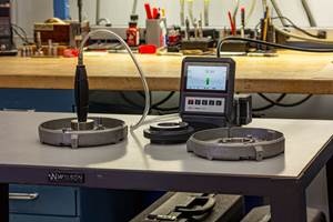
Standard: In gaging, a comparative measurement is obtained by comparing workpiece dimensions to established physical standards. These include gage blocks as well as master discs and rings. These standards must be routinely calibrated to ensure that they are even more accurate than the gages they are used to master. These standards should be handled as carefully as gage blocks, because nicks and scratches can be a significant contributor to error.
Workpiece: The measurement process must be appropriate to the workpiece. For example, centerless grinding often imposes a slight three-lobed condition on round parts. Most gages aren't designed to detect this condition and will register the part's average diameter rather than its effective maximum diameter.
What's more, it is dangerous to assume that just because a part feature falls within specified dimensions at one point, it will at all others. No part surface is perfectly round, flat or smooth. When a production process is under control, the amount of variation in roundness, flatness and so on is small enough so all points on the part surface fall within the specified tolerances. If the process is out-of-control, some points may lie outside of tolerances even though the gage indicates that the specific point being measured is in tolerance.
Instrument: In addition to being suitable for the specific workpiece, the gage must be in good condition, properly mastered and capable of holding calibration throughout a reasonable service period. Another thing to think about is how your customer might be measuring the part at the receiving end. You may check bores with an air gage, and your customer may check them with a mechanical gage. The air gage averages peaks and valleys, while the mechanical gage only measures peaks. Neither gage is “wrong,” but the results are not comparable either. This is where friendly or unfriendly disagreements occur.
People: Obtaining consistently good (for example, accurate and repeatable) measurement results is also a people issue. Have they been adequately trained to operate the measurement system and record the results? Are the operators assuming responsibility for proper gage care and maintenance? Checking for looseness, parallelism, nicks and scratches, dirt, rust, and so on is absolutely necessary to ensure system performance. It is only natural to cut corners if you are under pressure. It is also natural, perhaps even inevitable, for corner-cutting to result in a faulty measurement system.
Environment: Several factors in the environment around the gage must be considered. First there are dirt, dust and grease, the leading enemies of consistent, accurate gaging. Then there may be thermal influences from heating/air-conditioning systems, drafts, direct sunlight, nearby machines, a hot workpiece and even the operator's body heat. What about static electricity, magnetism, power surges, RFI/EMI and external movement that may be as obvious as vibrations from a nearby stamping press or as subtle as the water level rising and falling in a river several blocks away from the plant?
So before you kill the messenger, take a look at the total measurement system. Then, if you've done a thorough review and still can't find the problem, call your gaging equipment vendor.
Related Content
How to Choose the Correct Measuring Tool for Any Application
There are many options to choose from when deciding on a dimensional measurement tool. Consider these application-based factors when selecting a measurement solution.
Read MoreProcess Control — Leveraging Machine Shop Connectivity in Real Time
Renishaw Central, the company’s new end-to-end process control software, offers a new methodology for producing families of parts through actionable data.
Read MoreChoosing the Correct Gage Type for Groove Inspection
Grooves play a critical functional role for seal rings and retainer rings, so good gaging practices are a must.
Read MoreOrthopedic Event Discusses Manufacturing Strategies
At the seminar, representatives from multiple companies discussed strategies for making orthopedic devices accurately and efficiently.
Read MoreRead Next
5 Rules of Thumb for Buying CNC Machine Tools
Use these tips to carefully plan your machine tool purchases and to avoid regretting your decision later.
Read MoreBuilding Out a Foundation for Student Machinists
Autodesk and Haas have teamed up to produce an introductory course for students that covers the basics of CAD, CAM and CNC while providing them with a portfolio part.
Read MoreRegistration Now Open for the Precision Machining Technology Show (PMTS) 2025
The precision machining industry’s premier event returns to Cleveland, OH, April 1-3.
Read More


.jpg;maxWidth=300;quality=90)


