
The Point Of Error-Free Measurements
Test indicators are extremely useful and versatile test instruments. Spending a little time worrying about the details of the contact points will help improve the whole measurement process.

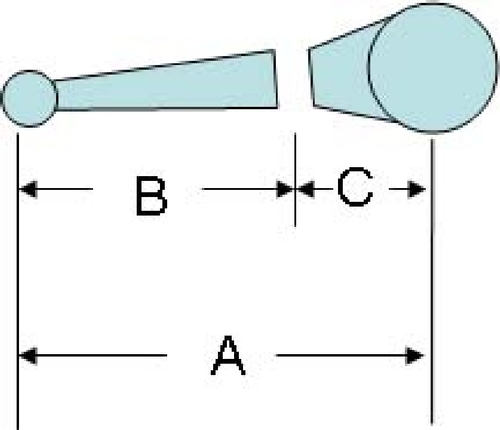
FIG. 2--With many test indicators, the contact point is really part of a two-piece assembly. One part is the actual contact point, the length "B." The other part is the pivot block that remains part of the test indicator, the length "C."
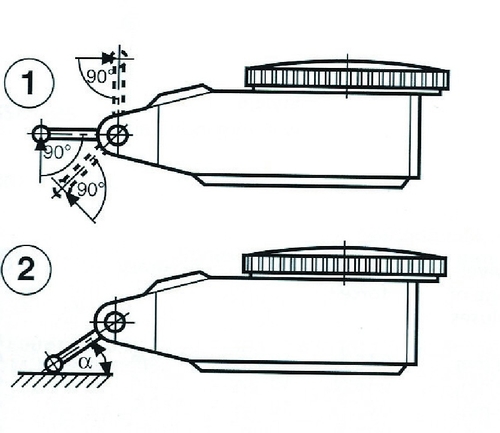
FIG. 1--With a test-style indicator, accuracy is greatest when the axis of the contact point is perpendicular to the measuring direction. This is seldom the case, however, and as the angle of the contact to the surface increases, the amount of vertical distance encompassed (change in height) also increases.

George Schuetz


Test indicators are often used in combination with a height stand and a surface plate, where either the workpiece or the stand can be moved around freely on the plate. When combined with a V-block or a pair of centers, test indicators can be used to test for roundness or runout on cylindrical parts. The angular motion of the test indicator’s lever allows the contact to ride easily over irregularities on part surfaces. This capability is lacking in dial indicators because the vertical-action plunger may resist responding to surface irregularities pushing “sideways” against the contact.
There are two user-influenced ways of operating a test indicator that can induce measurement errors. Cosine error is most typically seen with test-style indicators (or any lever-type electronic probe) during runout and concentricity checks on shafts and bores. It is also seen in engineering and tool making during checks of parallelism and alignment of flat faces.
With a test-style indicator, accuracy is greatest when the axis of the contact point is perpendicular to the measuring direction, as seen in Figure 1. This is seldom the case, however, and as the angle of the contact to the surface increases, the amount of vertical distance encompassed (change in height) also increases. The result is cosine error. Tables such as the one shown above, in which “A” is the angle between the probe and the surface of the part, can be used to correct for this error.
In circumstances where a large cosine error exists—for example, when the angle of the probe is greater than 30 degrees—it may be better to zero the comparator closer to the actual part size. This will minimize cosine error in the reading. To do this, select a zero master that is closer to the calculated reading than the actual standard size. In general, the rule is to always try to maintain the probe angle to within ±15 degrees. There are also special contacts available that help minimize this type of error by means of a special involute shape manufactured into the contact.
The other source of error has to do with contact point length. Like dial indicators, test indicators may require special, longer-contact points, sometimes as long as 4 inches. Gage readings generated by these test indicators will need to be adjusted to compensate for their length. Ratios are used to make these calculations based on probe length: for example, 2 to 1. However, while the contact may be designed properly, the actual contact as fabricated will have some tolerance referenced in the spec—a 2-inch contact may allow ±0.010 inch, for example—and the ratio may have to be adjusted accordingly. To avoid this problem, the test indicator should be calibrated with the probe as part of the measuring loop and any discrepancies should be calibrated out of the result.
It is important to calculate the lengths of these special contact points correctly. With many test indicators, the contact point is really part of a two-piece assembly: One part is the actual contact point, the length “B” shown in Figure 2, and the other part is the pivot block that remains part of the test indicator, the “C” length in the sketch. Occasionally, users will neglect to add in the “C” length, forgetting that the total contact point length is the “A” length.
Test indicators are extremely useful and versatile test instruments. Spending a little time worrying about the details of the contact points will help improve the whole measurement process.


Read Next

3 Mistakes That Cause CNC Programs to Fail
Despite enhancements to manufacturing technology, there are still issues today that can cause programs to fail. These failures can cause lost time, scrapped parts, damaged machines and even injured operators.
Read More
Encountering Surface Finishes in the Everyday World
Surface measurement is becoming increasingly important to ensure proper performance of a manufactured product. Advanced surface measurement tools are not only beneficial in the manufacturing industry but also have unconventional applications.
Read More
A History of Precision: The Invention and Evolution of Swiss-Style Machining
In the late 1800s, a new technology — Swiss-type machines — emerged to serve Switzerland’s growing watchmaking industry. Today, Swiss-machined parts are ubiquitous, and there’s a good reason for that: No other machining technology can produce tiny, complex components more efficiently or at higher quality.
Read More