Transferring CAD/CAM Files
Importing and exporting CAD files is a fundamental function of CAM software. An understanding of this process can help you know what to expect and will aid you when making a CAM purchase.
Share


CAM software today is bursting with new features. But before you are bedazzled by smoke screens, make sure you can do the basics first. One of your primary concerns when using CAM software is being able to import your customers' CAD files so you can generate tool paths and ultimately cut parts.
Transferring CAD files electronically is the norm, rather than the exception, for today's manufacturing world. In the past, shops relied on blueprints. But today you don't want to reinvent the wheel by re-creating a paper or electronic model. Beware of poorly developed CAM data translators. If you don't own a CAM package, see a demonstration of how the software imports files and cuts the most complex part in your shop. Import a file from every customer you work with to determine that there are no data-transferring issues before you cut the salesman a check.
What Is File Transfer?
File translation is a process in which one data format is converted into another. File translators are written independently by each CAD or CAM software company. Some design teams may use several different types of CAD packages to communicate with different teams or complete specific functions. One design model may be exported and imported into several CAD packages before the final file reaches manufacturing. Then you're counting on your CAM system's import translator to successfully filter through the result of the previous translations.
A common source of error in part files is receiving incomplete designs due to inexperienced or overworked CAD designers. You may not receive a complete model, or details that the translator is expecting may be omitted or lost. Or your CAM translator may not be fine-tuned enough for the specific CAD file format you are importing. So you will find the translating process offers plenty of room for error and miscommunication.
Types Of File Translators
There are numerous file formats on the market today. You can encounter IGES, CADL, DXF, ASCII, NCAL, PAR, PRT, SAT, SUP, STL, X_T, MODEL, the various European and American automotive formats, and other file extensions. Also, the CAD/CAM software manufacturers develop proprietary formats for their software. So one true conversion standard is not yet possible.
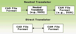
Currently, there are basically two types of file translators—neutral and direct. Neutral translators are used to convert a proprietary CAD or CAM data format into a generally agreed upon industry standard. They are documented and available for anyone to use. The primary neutral translators today are IGES for surface data and X_T or SAT, which were developed for solid modeling data.
The idea of using neutral file formats is a good theory. In reality, however, each CAD package has its own exclusive properties and methods for packaging geometric data. A common term in the industry is "flavors," which means that a CAD export translator will start with a neutral format, such as IGES, and may add its own unique slant. Therefore, the results are not truly common to all in the industry. A CAM package must interpret the modified neutral translator. As new versions are introduced, the CAD translators must also be revised. So, in turn, CAM companies must upgrade the importing translator specifically for each new CAD version to eliminate compatibility issues.
Direct translators can exchange data directly into the CAD software's proprietary format. The ability to integrate seamlessly between software packages is the best situation for manufacturing shops because data transfer errors are virtually eliminated. By directly transferring files you're eliminating the "middleman." In the end, less time is expended on data transfer issues so you're effectively reducing the product's manufacturing cycle.
Translating Successfully In CAM
A well-built CAM translator translates all types of files quickly and accurately. If you are unfamiliar with importing files, it is advantageous to read any accompanying CAM documentation on this subject that is shipped with your software. You may need to make simple adjustments to "flavor" your importing translator to a specific CAD package that ensures optimal conditions for importing files. Consult with your authorized CAM dealer or the manufacturer if you are unfamiliar with translators. Most often, problems originate from an incomplete design model that requires "tweaking" by a CAM programmer before proper tool path can be generated. Your CAM product should provide you with basic design functionality for correcting defective models. It should not overwhelm you with unnecessary design features that detract from your original purpose—machining your parts.
Importing Solid Models
You should expect your CAM translator to easily import both solid and surface models. Design analysis and simulation teams use the solid properties and prismatic shapes that can be created in the CAD solid modeler. Usually, these types of part features can be calculated against approximations. Tool path calculations need a more precise representation of the true shape of the part to avoid part gouging or tool interference. To obtain three-dimensional calculations, files are most often imported into CAM surface software. Even CAM packages claiming solid modeling capabilities may first translate model files into surface data, then reconstruct the solid, before generating tool path data.
Future Trends In CAM
Leading edge CAM manufacturers are driving the future of CAM software by providing direct "push-button product linking" with CAD manufacturers. Eliminating an extra conversion process of a neutral standard aids the manufacturing shop in obtaining the most seamless method for transferring data. Tool paths can be immediately assigned to the same design model.
Paul Keller, a mechanical engineer and project leader for the Rapid Model Design and Manufacture Initiative at NASA's Ames Research Center in California, is familiar with creatively linking tools. NASA Ames is a microcosm of industry, implementing several major CAD systems simultaneously at the Research Center. "Usually manufacturing shops run on separate, isolated systems," says Mr. Keller. "An ideal world would provide shops with flexible, interactive methods of data sharing." To that end, NASA Ames recently installed two dozen seats of SURFCAM, an independent CAM system, on "ruggedized" laptops to enable craftsmen to easily translate and send files to each other and to allow dynamic communication with the design team.
Mr. Keller is familiar with another industry issue that is important to many corporations and government agencies—the combining of all product information into a common data format throughout a product's entire life cycle. Data transferred cannot be limited to just geometry, such as curves, surfaces and solids. To manufacture a consistent, quality product also requires integrated analysis, manufacturing, implementation and testing procedures.
A solution is actively being studied. The International Standards Organization (ISO) is working with American, European and Asian businesses and government agencies to implement a standard for transferring electronic data, called the International STandard for the Exchange of Product Model Data (STEP). Essentially, STEP is a common structure, operating as a template, for sharing data among multiple users, across all functional areas.
"Communication among different departments and different software is a problem," says Mr. Keller. "Interaction is important for shortening the product life cycle. STEP will enable us to iterate designs based on manufacturing suggestions, then evaluate and analyze the results before manufacturing the pieces. It also offers a tremendous benefit for reusing and managing information from several engineering and manufacturing disciplines in an effective way."
There are several sections within STEP, called Application Protocols (APs), which are built into a common data model. These APs include definitions not only of typical geometry and drafting elements, but also of data types and processes for specific industries such as automotive, aerospace, shipbuilding, electronics, plant construction and maintenance. The most common AP in current use is AP203, which is focused on geometric elements for mechanical CAD. AP203 is further subdivided into classes for defining wireframe geometry, surfaces and solid modeling. To facilitate the transfer of information, STEP is built on a data exchange language, called EXPRESS, which formally describes the structure and correct conditions of a file's engineering information.
"The specification for IGES is written so that, theoretically, several interpretations are available, producing the different CAD flavors," says Mr. Keller. "The committees involved in writing the STEP standard are working toward eliminating the differences in reading entities, as in the case of IGES." Mr. Keller hopes that pressure from government contracts and large commercial users will require vendors and suppliers to validate their STEP translators and eventually eliminate variances in the interpretations.
Until STEP issues are resolved and there is one definite standard for data transfer, individual shops must continue to work with several CAD formats, depending on their customers' software requirements. Save time, money and labor by researching your CAM software and translators before you make a purchase. Although there may be issues beyond the control of CAM translators, well-written and robust versions can read and correct for many CAD data anomalies.
About the author: Denise Janowski is a technical writer at Surfware, Inc., the CAM developer, in Westlake Village, California.
Related Content
How this Job Shop Grew Capacity Without Expanding Footprint
This shop relies on digital solutions to grow their manufacturing business. With this approach, W.A. Pfeiffer has achieved seamless end-to-end connectivity, shorter lead times and increased throughput.
Read More4 Commonly Misapplied CNC Features
Misapplication of these important CNC features will result in wasted time, wasted or duplicated effort and/or wasted material.
Read More6 Machine Shop Essentials to Stay Competitive
If you want to streamline production and be competitive in the industry, you will need far more than a standard three-axis CNC mill or two-axis CNC lathe and a few measuring tools.
Read MoreGenerating a Digital Twin in the CNC
New control technology captures critical data about a machining process and uses it to create a 3D graphical representation of the finished workpiece. This new type of digital twin helps relate machining results to machine performance, leading to better decisions on the shop floor.
Read MoreRead Next
Setting Up the Building Blocks for a Digital Factory
Woodward Inc. spent over a year developing an API to connect machines to its digital factory. Caron Engineering’s MiConnect has cut most of this process while also granting the shop greater access to machine information.
Read MoreRegistration Now Open for the Precision Machining Technology Show (PMTS) 2025
The precision machining industry’s premier event returns to Cleveland, OH, April 1-3.
Read MoreBuilding Out a Foundation for Student Machinists
Autodesk and Haas have teamed up to produce an introductory course for students that covers the basics of CAD, CAM and CNC while providing them with a portfolio part.
Read More


