The Dynamics Of Better Drilling
Vibration is at the heart of a variety of common problems in machining holes. Mathematical analysis is helping to bring about a better understanding of hole-making processes...including how these vibrations behave, and what steps to take to bring them under control.
Share


Hwacheon Machinery America, Inc.
Featured Content
View More

Consider the three most fundamental chip-making processes: milling, drilling and turning. One of these processes stands out. In milling and turning, cutting takes place in the open, making it possible to learn a great deal about the behavior of the cut through observation alone. But in drilling—and in related hole-making processes—the action is hidden. No one can see what happens in the cut, and no unaided eye can see the machined surface unless the hole is cut open. This invisibility, as much as any other factor, probably accounts for why the mechanics of hole making have been so poorly understood.
One particularly important missing piece has been an applied understanding of self-excited or "regenerative" vibrations in hole machining. These are vibrations such as chatter that feed themselves simply as a result of the dynamics of the cut.
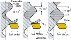
The phenomenon has been more fully mastered in other processes. In milling, for example, some manufacturers have learned to machine at harmonically stable cutting conditions that permit more productive cutting. When cutter oscillations in milling interact with the waviness of the part's surface, chatter is the result.
However, individual systems of spindle, tool and toolholder feature specific, repeatable harmonic speeds where cutter oscillation and surface waves cleanly bypass one another to keep the cut quiet and the cutting load level and smooth. (See the box on the next page.) By deducing and applying these stable speeds, manufacturers such as Boeing, for one, have achieved higher metal removal rates and wrung considerably more value from CNC milling machines.
But in hole-making operations, by contrast, there is relatively less science applied and relatively more intuition. Some hole-making operations perform superbly, some are inefficient, and the reasons for both the successes and the failures are often unknown. The ignorance costs manufacturers real money.
In Boeing's case, how much cost could be saved through more effective hole making could only be significant. Just one wing of a large jet aircraft may include 45,000 holes. Learning to machine these holes faster and with less tool wear would reduce the cost of machining. Learning to machine these holes rounder, straighter and smoother would reduce the cost of assembly. And a better understanding of vibration in hole making might be the key to realizing all of these objectives.
As part of the quest for a more refined understanding of what happens in the hole, engineers from Boeing's military aircraft group (St. Louis, Missouri) have been collaborating with researchers from the School of Engineering and Applied Science at Washington University (also in St. Louis) to develop a mathematical model of hole making that can predict and optimize the performance of real-world drilling and reaming operations. In time, the model will influence Boeing's choice of hole-making machine tools. For now, the model is already shaping the design of cutting tools and the way those tools are used.
One example relates to a reamer with very irregular flute spacing—so irregular that the six-flute tool includes two side-by-side flutes that have better than 110 degrees between them. It has long been known that an irregular-pitch reamer can produce a more stable cut, but one of the challenges has been to equalize cutting forces on such a lopsided tool so the reamed hole comes out with better roundness than the hole that preceded it. By using the mathematical model of the hole-making process, engineers were able to optimize flute spacing and other aspects of the reamer's design (precisely how they did this is secret) to account and compensate for the irregular forces. The result is a more effective reaming tool now used in the company's production process.
Achieving a model robust enough and accurate enough to be applied to such a specific, practical problem required not just calculus and computer analysis, but also a great deal of experimental test cutting to measure and define the influence of numerous characteristics of the tool.
Philip Bayly is an associate professor of mechanical engineering who leads this research on Washington University's side. He says the work began with Boeing's recognition (he cites Boeing's Jerry Halley and Jeffrey Luner in particular) that regenerative vibration may be key to many hole-making problems. The research that resulted has fleshed out some existing theories about how vibration works in drilling and similar processes . . . and how the nature of this vibration—particularly in drilling—differs significantly from the vibration that occurs in milling.
The most fundamental difference is this, Dr. Bayly says: In drilling, there may be two different types of vibration going on.
They affect the cut in two fundamentally different ways.
How Chatter Affects Tool Life
One type of drilling vibration is chatter, similar to the chatter that occurs in milling. In drilling, the chatter results from torsional-axial coupling, a mechanism inherent to the tool. Here's how it works:
As the drill cuts, it twists in reaction to the load on its cutting edges. The load is torsional, but the distortion of the drill also has an axial counterpart. The twisting causes the drill to "unwind." The drill wants to get longer. However, this extension is resisted by the thrust on the drill and by the drill's own axial stiffness. As a result, there are two competing forces in the hole: the torsional force trying to make the drill longer, and the opposing force that fights this extension. The drill flexes back and forth between these forces. The motion that results could be imagined to resemble a peck-drill cycle . . . but with the drill "pecking" only through microscopic strokes, and pecking on the order of 20 or 30 times for every single revolution of the tool.
The surface waviness from this cutting takes the form of a sun-ray pattern splayed about the bottom of the hole. Chatter occurs at any rpm where the drill's in-and-out motion interferes with the waviness left in the surface by the previous revolution of the drill. The rotating, oscillating drill collides with these waves, and the waviness and oscillation both grow more severe.
Precisely this effect creates the squeal so typical of drilling. During chatter, the tool, spindle and the rest of the system all resonate at a frequency close to some signature "natural frequency" of that system. And in most metal drilling operations, natural frequencies occur at values of cycles-per-second that match what the human ear interprets as sound.
The most damaging effect of chatter is the tool wear resulting from the jackhammer-like impacts. Chatter that is severe enough can cause a tool to snap. The vibration can be particularly destructive to carbide tools because—relative to high speed steel—carbide offers greater wear resistance but less resistance to shock. Carbide tools are therefore more likely to chip or crack as a result of the repeated blows.
But there are other damaging effects. The vibration may accelerate wear of machine components. And Dr. Bayly says the sun-ray pattern may also be significant, even for through-holes where the bottom of the hole disappears.
"Anything affecting the bottom of the hole is probably also affecting the side in some similar way," he says. And if something like the chatter pattern appears on the side of the hole, then this could affect the hole's fatigue strength.
Fixing Chatter
The best device for overcoming the chatter that occurs in drilling is the choice of spindle speed, Dr. Bayly says.
In drilling—just as in high speed milling applications where chatter is a major concern—the top speed is not necessarily the best speed. Instead, chatter-free drilling occurs when the speed at which the tool is spinning (in revolutions per second) divides evenly into the cycles-per-second frequency of the drill's torsional-axial vibration.
When these two frequencies are evenly divisible, this means the oscillation of the drill is perfectly following the wavy pattern of the surface. The result is smooth cutting with a steady and level chip load.
Zeroing in on this optimum spindle speed can be difficult—more difficult than it is in milling. One difficulty relates to gaging chatter's effect. Which of two milling spindle speeds is more stable can be judged by which one will permit a deeper cut. In drilling, trial-and-error test cutting can also be used . . . but here the lack of an objectively measurable parameter such as depth-of-cut complicates the task of judging which speed is chattering less when the audible differences are slight.
This is one of the main reasons why the mathematical model was developed. The model predicts optimum spindle speeds without the need for machining. However, the same model also verifies that there are several other steps shops can take to reduce chatter that have nothing to do with speed. These steps include:
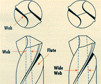
- Increase web thickness. The web is the central section of the drill between the flutes. (See illustration on facing page.) Instead of using a drill with a web thickness equal to 10 or 20 percent of diameter (which is typical), try a drill with a web thickness of 30 to 40 percent. The wide-web tool is stiffer and tends to chatter less.
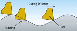
- Decrease lip relief. A drill with less lip relief tends to rub more against the bottom of the hole. This rubbing has a damping effect that can reduce chatter. The phenomenon is essentially the same as the process damping that accounts forwhy worn tools often chatter less. (See the box on the previous page.)
- Increase feed rate. Increasing the penetration rate relative to rpm is another way to encourage more rubbing.
- Decrease helix angle. This is the least well-known of all of these suggestions, Dr. Bayly says. Among the drill characteristics studied by researchers is the coupling between torsional and axial deflection. The findings show a clear relationship between helix angle and chatter. With a smaller helix angle, the drill will "unwind" less in response to an axial load . . . meaning the drill won't "peck" through such a large amplitude.
How Low-Frequency Vibration Affects Hole Roundness
All of the discussion so far has focused on chatter—the regenerative vibration occurring near the system's natural frequency. In milling, this may be the only such vibration that significantly affects the process. But drilling is more complex. While the tool is chattering in and out at some high frequency, it may also be swaying back and forth at a much lower frequency—essentially tracing a cone-shaped volume as the swaying tool rotates. This low-frequency vibration is also regenerative in that it creates waves in the resulting form that tend to exaggerate the severity of the vibration itself. However, this vibration is not chatter per se, because it has nothing to do with the system's natural frequency. Instead, the frequency of this vibration tends to be a multiple of the rotation speed, whatever that speed may be. This direct link to the spindle speed makes low-frequency vibration particularly insidious, Dr. Bayly notes. With this type of vibration, adjusting the spindle speed is not going to help.
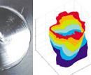
The swaying motion from low-frequency vibration shapes the roundness of the hole. The vibration occurs in drilling and reaming both. Holes that result from this vibration feature out-of-round lobes occurring in odd numbers. A typical shape is a three-lobe hole vaguely suggestive of a triangle. (See photo) Holes with five and seven lobes are also possible. Though any of these holes may measure the correct diameter, the same hole may not accept a fastener of the corresponding size.
This type of vibration is often misdiagnosed as the tool "walking." That description of the tool's movement fails to account for the regenerative effect. The tool is actually swinging through regular strokes like a pendulum, completing back-and-forth cycles typically at a rate of two, four or six times per tool revolution. The lobed shape that results (the number of lobes always equals the frequency per revolution plus or minus one) encourages and amplifies this vibration as the cut continues.
Fixing Low-Frequency Vibration
Changes to either speed or feed rate will do little to address the hole-roundness problem. However, all of these steps have been shown to have an effect:
- Increase stiffness. Using a more rigid tool can reduce low-frequency vibration just as it reduces chatter.
- Increase the number of flutes. Instead of a two-flute drill, try one with three or four flutes. The greater number of flutes encourages the formation of more numerous, smaller lobes—bringing the hole closer to the intended round shape.
- Increase margin contact. The margin is the surface that trails past the cutting edge on the side of a standard drill's flute. Some makers of higher-performance twist drills have reduced margin width to minimize rubbing on the side of the hole. However, a step in the opposite direction can be beneficial where low-frequency vibration is concerned. Increasing the number of margins on the tool can help support the drill. In addition, if the rubbing happens to occur at a spot where it can interfere with regeneration, then this effect may damp out vibration in the same way that reduced lip relief may damp out chatter.
A double-margin drill increases the number of margins. This type of drill adds a second margin to each flute in addition to the one that touches the cutting edge. By doubling the number of contact areas around the circumference of the tool, this drill increases the chance that rubbing will occur in just the right spot necessary to improve roundness.
Research into low-frequency vibration continues, Dr. Bayly says. Other factors researchers are studying include the role of point geometry, and the role of other couplings in drill deflection beyond the axial-torsional coupling.
"Low frequency vibration is a more stubborn problem than chatter, and also a more serious problem," he says. "With chatter, even if tool life is very low, you can still drill a good hole. But low-frequency vibration can make it impossible to produce a hole that's acceptable."
Looking Ahead
Dr. Bayly is now in discussions with the developer of a software product sold for metalworking process analysis. Those discussions may lead to the commercial availability of some of the predictive algorithms that have resulted from the hole-making research.
For now, the beneficiary of this work is Boeing. The company has already applied the mathematical model to improve both cutting tools and cutting conditions for various hole-making operations. In the future, Dr. Bayly says, the model will help Boeing specify machine tools as well.
He can say this with some confidence because the understanding of vibrations where milling is concerned has already begun to influence the company's choice of machine tool hardware.
"The kinds of characteristics that let us specify a machine today are thrust, torque and horsepower," he says. "For new machines purchased in the future, that list of specifications will grow."
Damping, natural frequency and dynamic stiffness might all be added to the list of Boeing's requirements for hole-making machine tools. For these characteristics, the mathematical model makes it possible to forecast what values would work best for a proposed hole-making operation.
"Soon we won't just say to the machine tool builder, "I need a machine with at least 30 horsepower,'" Dr. Bayly says. "We will also say things like, "I need a stiffness of at least 10,000 newtons per millimeter.' Or, "I need a natural frequency of exactly 2,000 hertz.'"
Related Content
Briquetting Manufacturer Tools Up for Faster Turnaround Times
To cut out laborious manual processes like hand-grinding, this briquette manufacturer revamped its machining and cutting tool arsenal for faster production.
Read MoreFinding the Right Tools for a Turning Shop
Xcelicut is a startup shop that has grown thanks to the right machines, cutting tools, grants and other resources.
Read MoreHow to Troubleshoot Issues With Tool Life
Diagnosing when a tool is failing is important because it sets an expectation and a benchmark for improvements. Finding out why gives us a clue for how to fix it.
Read MoreQuick-Change Tool Heads Reduce Setup on Swiss-Type Turning Centers
This new quick-change tooling system enables shops to get more production from their Swiss turning centers through reduced tool setup time and matches the performance of a solid tool.
Read MoreRead Next
Registration Now Open for the Precision Machining Technology Show (PMTS) 2025
The precision machining industry’s premier event returns to Cleveland, OH, April 1-3.
Read MoreBuilding Out a Foundation for Student Machinists
Autodesk and Haas have teamed up to produce an introductory course for students that covers the basics of CAD, CAM and CNC while providing them with a portfolio part.
Read More5 Rules of Thumb for Buying CNC Machine Tools
Use these tips to carefully plan your machine tool purchases and to avoid regretting your decision later.
Read More.png;maxWidth=970;quality=90)


.%20The%20effect%20can%20be%20seen%20in%20the%20workpiece.jpg;width=860)





%20were%20mechanically%20vibrated%20during%20cutting%20on%20a%20lathe.jpg;width=860)



.png;maxWidth=300;quality=90)


